Right Flap Brace and Aileron Gap Fairing

December 12, 2011

Prev | Next

Alright, before we get too busy getting excited about two posts in a row, let’s talk a little about Christmas. This year, we decided to do a Christmas tree. A few Saturday’s ago, we ventured out into the cold (it was pretty warm) and cut down our own tree (no we didn’t, we bought it from the farmer’s market).

Anyway. There are three interesting pictures from the day.

Jack, incredulously watching us decorate the tree.

Ginger's falling asleep. OMG this is the closest she's been to feather's since FEATHERGATE.

Finally the tree.

Now it needs some presents. Send me some presents.

Just kidding.

Let’s get back to building, shall we?

Tonight, high on the excitement of flipping the right wing over, I decided to get some more aluminum down from storage.

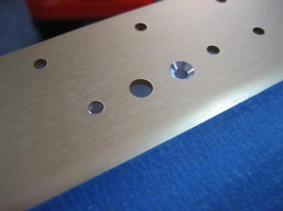
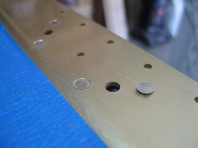
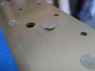
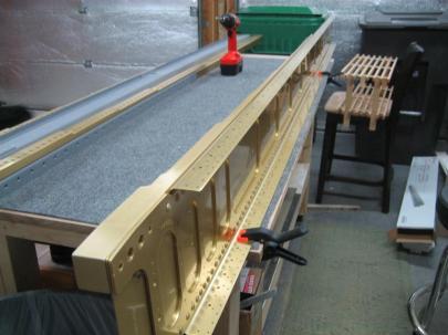
These two pieces are the Aileron Gap Fairing and the Flap Brace.

Part numbers shown for the right wing.

Turns out these have been in the garage for over a year now, so when I pulled off the blue vinyl, there was some residual…well…residue.

A little acetone fixed this right up.

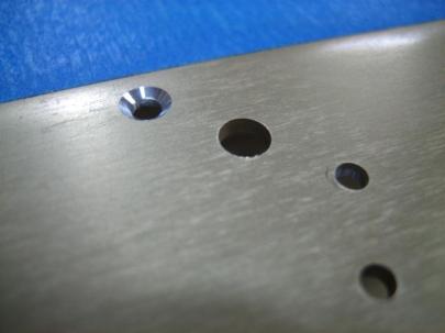
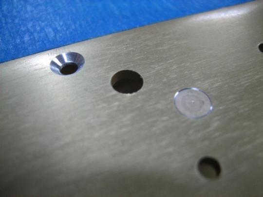
I scuffed these up quickly (I’ll do this more completely when I’m about to prime) and got out the right aileron brackets. The top of the inboard bracket was interfering on my wing (like everyone else’s before me), so like them, I ground down the top corner a little with the scotchbrite wheel.

Here's the corner I ground down.

And clecoed in place.

The outboard bracket clecoed in place.

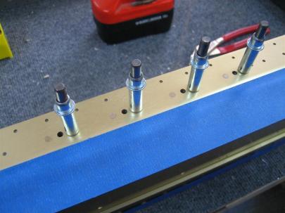
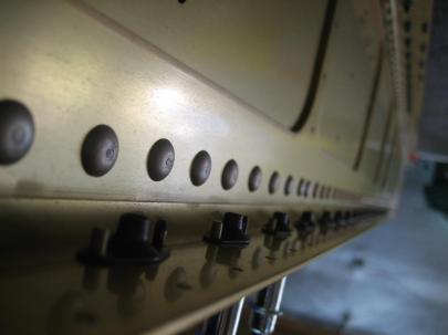
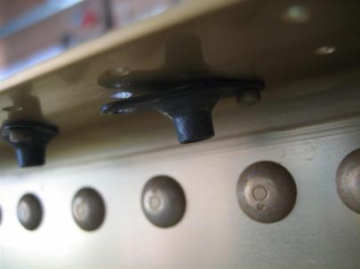
Here’s the flap brace, looking inboard.

I'll matchdrill both sides, but only rivet the brace to the spar now, the skins will come later.

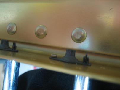
The flange on the inboard most section is sitting a little funny, so tomorrow, before matchdrilling, I’ll see if I can’t straighten this out a little.

Crooked flange.

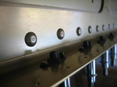
Flap brace looking from inboard to outboard.

Then, I clecoed on the aileron gap fairing.

With no trimming, look at how nicely everything lines up. Man, this is easy.

30 short minutes tonight, but it’s better than nothing.

Prev | Next


Started the Left Flap

October 6, 2011

Prev | Next

THE CHANGING OF THE PLANS!!!! [triumphant music]

Wuhoo!

Okay, this time, I’m going to be smart, and start with the left flap (the one that’s depicted on the plans).

First, I found some parts, then pulled the blue vinyl off the spar and ribs.

That longer rib on the left is actually the wrong part. I assumed there was a L and R of the long ribs (forgot the part number), but those ribs actually are L-L for the left flap and R-R for the right flap. (The flanges of both ribs point outboard.) Weird.

Anyway, the directions have you mock the ribs up with the spar, then drill.

One thing that caught me was the #40 prepunched hole for the ribs, where they will be drilled to #30. Van’s doesn’t usually do this, but I confirmed on the plans (below) that LP4-3 blind rivets will go here eventually.

Weird, but okay...drill drill drill.

I love the very beginning of a new part because it goes together quickly.

See!? I'm already clecoing on the bottom skin!.

WHOA. Van’s basically tells you in the instructions that you will need shims between the “rear spar” and the aft end of the ribs. Why don’t I need any?

They must have tightened up the tolerances on the pre-punching.

I guess I don’t need to make those shims…

Anyway, after flipping it over…

It's starting to look like an airplane!

…I got a visit.

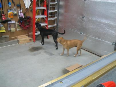
Ginger looking at the airplane, Jack sniffing.

Jack looking at the airplane, Ginger sniffing.

They also eat, sleep, and poo… (I can’t believe I used “poo” in my blog. Sorry, mom!)

Back to work!

I do need two spacers per flap, so I made four now.

Here's where they go. I'll drill the other hole later.

Next, they ask you to get the hinge out and start drilling it.

Hmm. I’m not quite ready for this tonight. I got it aligned with where I think it should be, but I want to sleep on it (and more importantly, surf some other build sites to make sure I’m on track.)

Hinge aligned, but not drilled yet.

Maybe tomorrow….

1.0 hour, and I feel like I got a lot done.

Prev | Next


Riveted Right Wing Top Skin Wingwalk Area

August 4, 2011

Prev | Next

I think we need a little non-airplane excitement in our lives. Let’s start with a little movie.

I never get tired of letting them howl at those sirens. Ginger does a pretty good job of matching the pitch. Jack’s just going NUTS.

Okay, back to building.

Well, I finally conned someone from work to come over and help me rivet some top skins. We’ll call this person Joe to protect the innocent.

Joe was eager to learn about the RV-7, so after a very quick tour of the shop, we got to work.

First thing, we pulled out my old practice kit, and we looked at some of my riveting, showing him where some where okay, some were perfect, and some were horrible.

After that, we got the rivet gun out, turned it on low, and I let him hold it against the bucking bar to get a feel for the feathering trigger, what it feels like to hold, etc. After a few minutes, we put some AN426AD3-4 rivets in the trailing edge of the practice kit, and practiced our shooter-bucker teamwork. After 3 or 4 rivets, we had the air pressure dialed in to something comfortable, and it clicked for Joe. 5 perfectly shot flush rivets.

Our practice setup.

Well then, let’s get started.

Note: I am totally ignoring the “start in the center rib of each skin” advise from Van’s. It supposedly works out to the tightest possible skin, but I don’t understand how anything will move around after precisely drilled these holes and dimpled (and 50% clecoed). I don’t know. Maybe I’ll end up with the world’s wrinkliest skin. Who knows.

Anyway, we stuck rivets into every other hole (remember, I’m crazy and 50% clecoed this beast) and got to working. We had a good “ready…go” system down, and we got a few good rivets in.

Joe's first rivet. Perfect.

The very next rivet? Not so good. I let the bucking bar slip off the shop head, and the rivet gun left the tiniest hint of a ding. Lucky for us, we decided to start in the middle of the wing walk rib, so any dings (polish or paint) would be under the wing walk nonstick strip. We are so smart.

Not two minutes after I explained that it’s a rite of passage to knock over the rivet container, and not to worry about it.

I look under the wing skin and what to I see?

HAHAHAHAHAHAHAHA!

Sorry, Joe. We’re laughing WITH you. I promise.

Okay, we got the 3 remaining wing-walk ribs 50% done…

Halfway done.

Look at these perfect shop heads!

Then pulled out the remaining clecos, put rivets in the empty holes, covered each head with tape, and shot the remaining rivets.

On the inboardmost trailing edge rivets, I totally butchered a shop head trying to use my tungsten bucking bar which slipped off the head. Luckily, the skin wasn’t dinged, but we had to drill out the rivet and reset it. It went great, and I finally got to use the $10 Harbor Freight Body Repair Kit I bought a year ago.

This bar worked perfectly.

Some more riveting… and we finished the wingwalk area.

This looks so sweet in person.

I can’t believe that some day I’m going to be standing on that. (I can’t believe someday some of you loyal readers will be standing on that!)

Only two mistakes tonight, and both of them were my fault. Joe 2, Andrew 0. Boo.

1.5 hours (I’m NOT going to count it as 3.0 man-hours). 72 rivets, only one of the drilled out. Thanks, Joe!

10AUG2011 UPDATE: I am going to count Joe’s hours. I’m changing the log to count it as 3.0.

Prev | Next


Preparing the Right Top Skins

August 1, 2011

Prev | Next

Well, what was supposed to be a few minutes in the garage clecoing the skins to the skeleton turned into 2.5 hours. I hate it when that happens. /sarcasm off.

First up, I need to “clean up” the dimples in the rear spar. I used my countersink for this, and just let it spin a few times in the hole.

Easier than it sounds, I promise.

Then, I started 50% clecoing some top skins on.

First the inboard skin...

(I didn't HAVE to removed the blue vinyl at this point, but I did.)

Then the outboard skin.

A view from the outboard side.

At this point, I had spent about 30 minutes getting the skins on. Nice easy day….uh oh.

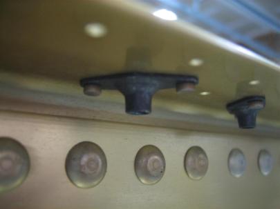
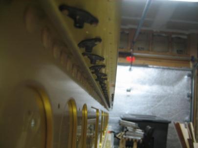
I forgot about torquing on the tiedown brackets.

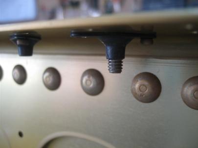
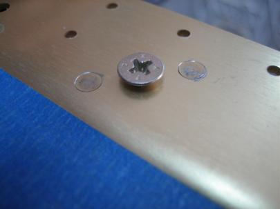
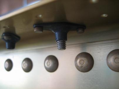
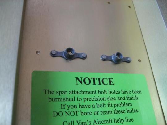
I have to admit. Early on, I waiting on installing these permanently because I thought I heard someone say that you have to take it back off to get the aileron bellcrank bushing in place. Well, that’s true, but you just have to take the bellcrank brackets off, which are the four bolts that screw into the nutplates (shown below) from the accessible side of the spar. You DON’T have to remove the whole tiedown bracket.

Jeesh.

So, guess what I got to do AGAIN!?

Yup. Take off the tank so I could reach the tiedown bracket bolts with a torque wrench.

Tank off. Torqued. (I don't have any torque seal yet, so I'll have to do it from the bottom, which is the right way anyway, so the torque seal is visible.)

I think I wasted another hour getting the tank off and back on, especially since I put the z-bracket bolts in first on the way back on, and one edge of the tank skin wasn’t sitting perfectly, so I had to take all the skin screws back out, loosen the z-bracket bolts, then put the skin screws back in, and then tighten the z-bracket bolts.

God, I hope that’s the last time I have to remove the right tank.

Later that night, we opened some wine, and the puppies decided to be extra cute.

First, here’s Jack.

Awww. (Yes, she's holding TWO glasses of wine. But I know what you are thinking, and sadly, one of them is mine.)

Ginger was being the shy one tonight. (Hiding in the man-chair.)

Double Awww.

2.5 frustrating hours. Skin riveting next, though.

Prev | Next


Right Tank Rib Prep

June 14, 2011

Prev | Next

Not much today, but here goes anyway.

I had approximately half a syringe full of proseal in the freezer from Saturday (I think), and it was going to go past its 4 days of freezer goodness, so I pulled it out and made my rivet encapsulation dollops (umm, spelling?) a little bigger.

I still have good pathways for water, but just wanted to be sure I sealed those puppies well.

Same thing on the cap flange, except these don't look as pretty.

Then, I spent some time deburring and dimpling tank ribs.

Two done.

Dinner time!!!

For extra credit, this picture has Jack and Ginger, too!

After some more rib prep, I have 6 of the 7 ribs clecoed in place.

(Still working on the inboard rib.)

My gameplan from here onwards will be to finish up the first rib, then work on the outboard rib (there’s a reinforcement plate I have to drill), then pull one (or two) ribs out at a time, clean judiciously, put sealant on the flanges, 100% cleco in place, then rivet.

Then, make fillets, do some rivet encapsulation, and celebrate with beer.

I’m planning on one rib per night, but might get in two. Just a few more nights of miscellaneous work, then I can get started.

1.0 hour.

Prev | Next


Finished Matchdrilling Right Wing

February 12, 2011

Prev | Next

As far as YOU’RE concerned, it was a pretty boring night in the shop.

All I did was move about 500 clecos one hole over and then matchdrill the remaining holes in the right wing bottom skin. No big deal, but now the whole right wing is done being matchdrilled.

Per the instructions, I can remove the bottom skins and get to work on the tank.

Instead, I’m going to get back to work on the left wing, and then get to work on both tanks at the same time.

Because of all the pictures in the last post, I’ve decided to go easy on the repetitive picture thing.

This time, everyone who is reading is rewarded with this:

Jack and Ginger, walking each other down the street.

Half an hour.

Prev | Next


Roll Your Own In-Ear Headset

February 4, 2011

Prev | Next

Well, after some thought, and inspiration from watching the VAF thread on cheap in-ear headset alternatives, I decided to sacrifice my cheap backup headset (and about $15 from Radio Shack) and try my hand at this in-ear headset thing.

My mom got me these really nice in-ear headphones for my birthday last year (thanks, Mom!), and I’m going to design this thing around those.

I’ve done a ton of research, but still feel a little uneducated. After finishing, I feel much better.

I started at Cozy1200.com, then moved on to wikipedia to teach myself about TRS connectors, audio-taper potentiometers, and then audio output transformers.

Okay, now that you are an electronics expert, read on.

Here’s everything I got from Radio Shack. Since I’m sacrificing an existing headset, I didn’t need the jacks, plugs, and microphones from aircraft spruce or anything.
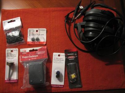
Christmas in February. Total cost ~$15.

Upper left is assorted grommets – $2

Right from there, two stereo 1/8″ panel-mount jacks – $3

Lower left is a 5K Ohm audio-taper potentiometer – $3

Then a 3″x2″x1″ project enclosure (perfect size) – $2.50

Then two 1/4″ knobs (for the potentiometer) – $2

Then an audio output transformer – $3
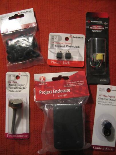
A little closer shot so you can see things more clearly.
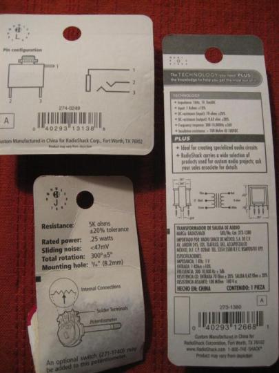
The back of some of the packaging. None of this information was helpful.

Okay, let’s get to sacrificing!

I peeled off the ear cups of my old headset, pulled back some foam, and saw a couple screws.
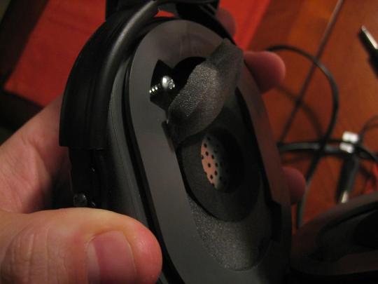
I was trying to make this non-permanent in case the project didn't work out, so I'm trying to be really careful.
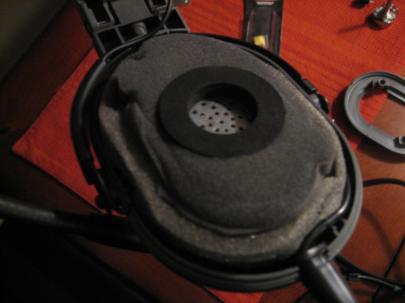
Plastic cover off.
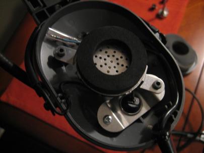
Pulled out the foam.
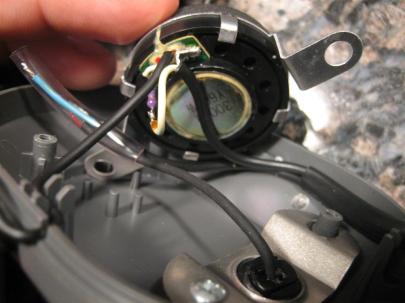
Then lifted the speaker.

The source electrons are coming in from the cord on the right. One conductor pair connects to the micrhone wires and goes back to the bottom right, which is an exit for the mic boom. The other pair goes through a resistor on the speaker and then on to the speaker in the other ear cup.

Since I am using my nice audio headphones, I don’t need to worry about the speaker stuff.

I carefully marked the microphone wires and heated up the soldering iron to start taking stuff apart.

After getting the wires disconnected, I unscrewed the retaining plate (lower right corner of the previous picture) and took apart the little plastic ball that holds the boom in place.
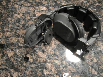
Headset with no more connections.

Sweet. Now I have what I need, the mic, boom, and cords that go to the proper aviation style jacks.
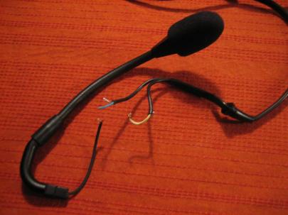
Green plus shield is for mic, yellow plus shield is for speakers.
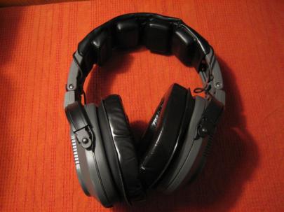
I put the headset back together so I could still use it for noise attenuation.

I had this grand plan to not even touch the mic wire. I’d just let it run straight through the project enclosure.

I stripped a little covering off of the wiring run and tried to figure out which wire to cut.
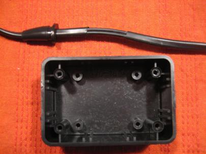
This is going to work great.

Then, I proceeded to find the mic wire, run my finger down to my now stripped wire run, and…

CUT THE WRONG WIRE!!!!!

Ugh.

So, I went ahead and cut both.
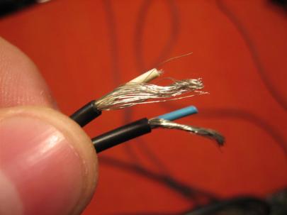
Here's what they look like up close.

Before I get too far with wiring, I need to figure out how this potentiometer works.

First, I hooked up my multimeter across the two outer terminals, and it read 4.65 KΩ no matter what the position of the pot.

Then, I hooked up my multimeter across the left and center terminals, and it read 0.00 KΩ when turned counter clockwise and 4.65 KΩ when turned counter clockwise. (I want a lot of resistance (no signal) when it’s turned counterclockwise).

Sure enough, when I hooked it up to the right and center terminals…
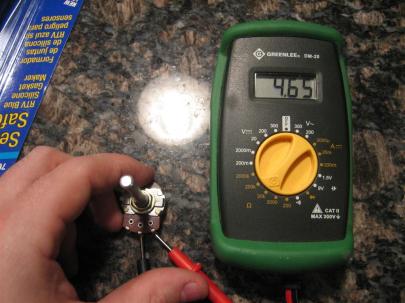
...4.65 KΩ when turned counter clockwise...
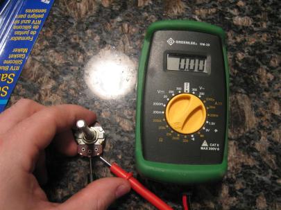
...and 0.00 KΩ when turned clockwise.

Now, let’s attach the knob.
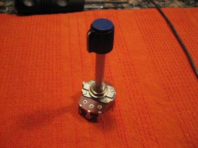
Umm... down in front?

I took it out to the garage and did a little metal removal.

Then, back inside to drill a few carefully place holes in the project enclosure.
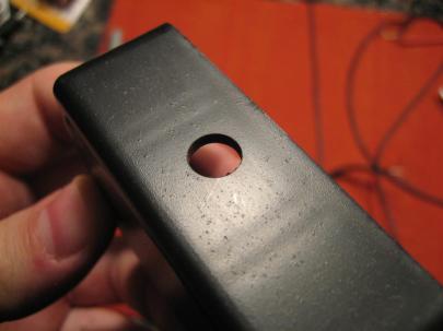
It's a hole!

Okay, I’ve thought carefully how I want this laied out. I’m going to lay this thing on it’s edge to the left of my left thigh when flying.

So, the volume knob is on top, the wires going to the plane jacks can go forward (or aft, because the knob turn direction is constant no matter which way the box is rotated), and the microphone and headphone jack will be on the other side.

Clear as mud?
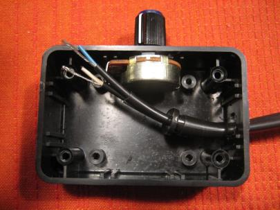
There's the knob on the potentiometer. (It barely fit).

Then, I pulled out some of the other parts. Here’s my stereo 1/8″ (phone) jack that works with most headphone plugs.

Note: My original headset is mono, so instead of pulling apart the plugs to make it stereo, I’m going to make a mono version to make sure this all works out okay. If it works well, I may try again, this time in stereo (with some music inputs, perhaps?).
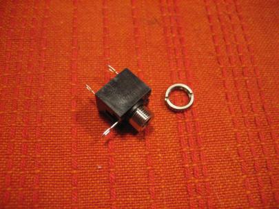
Stereo jack.

Okay, then I moved on to this really weird critter, the audio output transformer.

Without going into too much detail, there is a primary side which connects to the high impedance part of your circuit, and a secondary side, which connects to the low impedance side.

I looked at my proposed audio panel (GMA 240) and it’s output is rated at 150Ω impedance. I looked up my Klipsch headphones, and they are 18Ω impedance. I looked at my trusty David Clark headset (which seems to work great in every airplane) and it is 300Ω per speaker, or (since they are wired in parallel), 150Ω total impedance.

So I need to bump the 150Ω down to 18Ω.

“But Andrew”, you say, worriedly. “You bought a 1000Ω to 8Ω audio output transformer!!!!”

Yes, but (from my quick conversations with some of our avionics guys) the transformer is really a ratio thing.

Let’s say I just plugged my headphones into the jack. Since they are such low impedance, the audio coming from the panel would overdrive my headphones (because it’s putting enough power out for a higher impedance speaker). I’d turn the radio down so far for a correct volume that the guy (or girl) in the other seat wouldn’t be able to hear anything.

Really, it’s more important that the headphones are matched impedance, within reason of the audio output.

Anyway, if I bump down the 150Ω  by a ratio of 1000/8, it would be something like  1.2Ω. That’s no good.

Based on the back of the transformer packaging, I tested the Primary side (the one with green, black, and blue wires) of the transformer for DC resistance. It was supposed to be 70Ω.

When I tested the Green and Blue, it was 70Ω. When I tested the black and blue, it was 35Ω. Yes! I think I read something about this! I’ll just use black and blue and theoretically, I’ll get 150*(8/500) or 2.4Ω. Not exactly 18Ω, but better than overdriving the headphones.
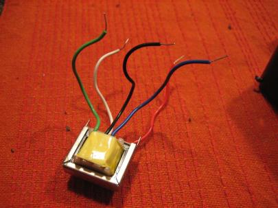
Audio output transformer, primary (1000Ω) side up.

Okay, let’s run some more wires so I can start putting this bad boy together!
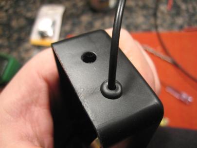
A couple of 1/4" holes for some grommets (that's the mic wire coming out) and the headphone jack.

Then, I soldered the microphone wires back together just like they were in the old headset cup.
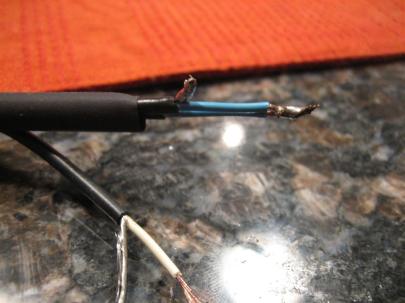
Not pretty soldering, but it will do.

Then, I hooked up the white wire from the secondary (8Ω) side of the transformer to the poteniometer.

And a little heatshrink (which has some solder on it...oops) for vibration resistance.

Then, I turned my stereo jack into a mono jack. (Remember from your wikipedia reading that tip is left, ring is right, and sleeve is ground.)
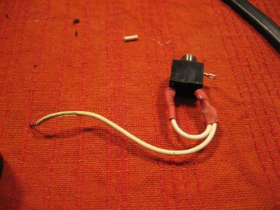
Sweet.

Then I hooked up the other wire of the secondary side of the transformer to the jack.
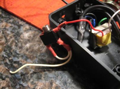
I'm getting close.

Then, the left/right side of the jack to the center connector of the potentiometer.
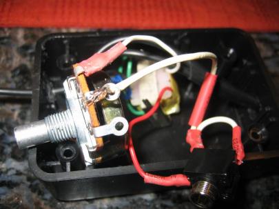
It's starting to get a little messy.

Then, very delicately mount everything and push everything into the box.
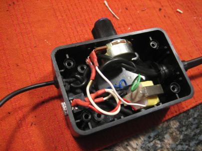
I think It's going to fit!!!

WUHOOO!
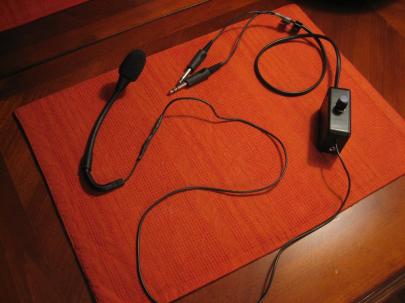
This is sweet. I can't believe I made this!

So, the existing mic from the old headset will somehow me mounted to my head (people have used heatshrink-covered piano wire, etc.), then that wire will go down, through my control box and into my audio panel through the old jacks.

My nice earbuds will plug into my control box, then go through the potentiometer (for volume) and the transformer (for impedance matching) and then to the audio panel.

As a test, I plugged my David Clarks into my home stereo system and set it to a reasonable volume. Then, I pulled in my new earbuds into my DIY headset box, then into the stereo (having turned down the volume on the box) and then slowly started raising the volume without touching the stereo system volume. When I got close to full volume, the volumes MATCHED!

WUHOOOOO!

I’m going to trust that the microphone works just like it did before, since all I did was unsolder and resolder. Now that I know the volumes match, I’m pretty sure this thing is going to work.

Tomorrow at work I’ll plug them in and see how it works.

Someone’s going to need to give me a ride in their airplane so I can compare the David Clarks with the new headset. (I’m also curious to see if my Klipsch earbuds are going to be as noise-attenuating as they are normally.

Another great night! (Doesn’t count as build time, though, since it’s not RV specific.)

Prev | Next


Tank Attach Nutplates, Left Upper Spar Flange

October 23, 2010

Prev | Next

After getting a ton of housework done, I managed a quick half hour in the garage to finish up the nutplates on the left spar.

I took some pictures, but they are just like the ones from the previous post, so I’ll be short with the descriptions.


Countersinking.


I found it a little quicker (and less tiring on the drilling arm) to do 4 at a time. I’d countersink four sets of holes for the nutplate attach rivets, then cleco one side of a K1100-08 nutplate in, squeeze the rivet, and then take out the cleco and rivet the other side in. Then move on to the next four.

I’m sure it didn’t actually save me any time, but for some reason it seemed quicker.


Just squeezed the first four rivets on this flange.


Nice looking shop heads, if I do say so myself.


Another angle, I guess?


Remove the cleco.


Put in the other rivet (man, I was really camera happy today...)


Everything was going great until the VERY LAST RIVET.

[sigh]


For some reason I lifted up the squeezer as I set the rivet.


Another angle (except it's the same angle). Sorry.


After successfully drilling the rivet out. I was left with a crooked nutplate. Hmm.


Problem solving time!


I didn’t have a clamp small enough to hold the nutplate in place while I reset the rivet, so I grabbed one of the #8 screws (forgot the part number, sorry), and screwed it in gently.


Wuhoo! I think this is going to work!


asdf


(Screwed in gently) because I hadn't countersunk yet. This worked great.


See, I told you it worked great.


Last, but not least, I squeezed the AN426AD3-6 rivets for the K1000-4 nutplates near the spar root.


Flush side...


Nutplate side.


64 Rivets, ONE drilled out  in 0.5 hours.

Oh, and then I went for a run with the pups. (And by run, I mean rollerblade.)

Prev | Next


Tank Attach Nutplates, Left Lower Spar Flange

October 21, 2010

Prev | Next

With the girlfriend gone for the night, I managed to clean up all of the electrical stuff I had out messing around with my wig-wag experiment, and pulled the left spar out of the box. Here it is, in all of it’s golden glory.

Golden Glory!

First step is to countersink the tank (and access plate) nutplate attach holes. First, you have to run a #40 drill through the holes or else the countersink pilot won’t even fit in the hole. Here’s one of my first countersinks on the left spar.

I went back and cleaned this one up after testing with a AN426AD3-11 rivet (-11 because it's easier to get back out while testing countersinks...it's so long you can just push it back out from the back.)

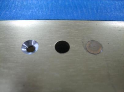
These countersinks are a little better. (The one on the right is a tad deep, but should be okay because these are just nutplate attach holes.)

I left the door to the house open so the pups could come out to visit.

Hey guys (Jack and Ginger).

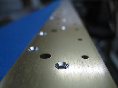
Hey Andrew, how about one of those artsy shots down the spar after countersinking the nutplate attach holes?

Sure, here you go.

Then, I pulled the K1100-08 nutplates out for the tank attach holes and the K1000-06 nutplates out for the access plate holes, then clecoed one side in, and put the required rivet (AN426AD3-4) in the holes.

Where’s my squeezer?

It's right there on the table, dummy.

Then I squeezed some rivets and removed the clecos.

Squeezed (repeated 41 more times.)

Other side done. (Repeated 41 more times.)

Under the hood, things look good. I still like this new Cleveland main squeeze much better than my economy squeezer.

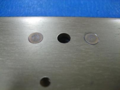
Pretty shop heads.

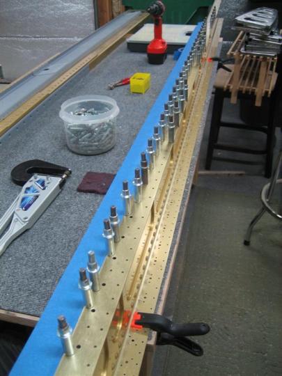
Down the row.

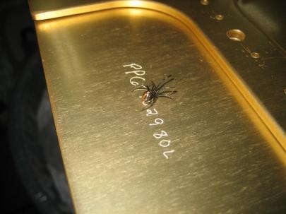
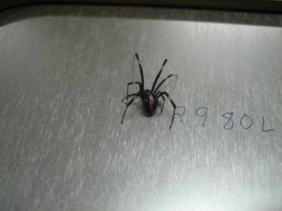
I then laid the spar down and saw this guy.

Yikes.

Whoa. Scary.

After a little internet research, I think I’ve figured out he (actually she due to her size) is a red-back.  I’m going to keep looking though. I don’t want it to be a red-back.

1.0 hour. 84 rivets.

Prev | Next


Prepped Right Wing Main Ribs, Clecoed Skeleton

September 18, 2010

Prev | Next

I’ve been at a little bit of dilemmna the last few days trying to figure out what direction to take with the project.

I still have the left rear spar to work on (until the left main spar shows up from Van’s…shipped yesterday…should be here Wednesday), or, I could move ahead with some rib prep on the right wing.

For the sake of  seeing something cool at the end of the day, I think I’ll move ahead with the right wing, and hopefully I’ll be able to get it onto a wing stand (yet to be designed) by the time I can get the left spar caught up to this point.

With rib prep, I’ve decided not to follow the suggestion to do all the ribs at once. I’m going to do them a few at a time to save my sanity.

First thing, let’s find some ribs.

I've pointed out to you before that I am at a little bit of a disadvantage building the right wing first, from the plans that only show the left wing.

Notice here that of the three different kinds of main wing ribs, there are both left and right versions in each of the wings. From what I can tell, the flanges face left or right based on what will be easiest/accessible to rivet.

So here are some main ribs (I count 11 in the picture, there are really 14 main ribs in each wing).

My goal today was to get the ribs clecoed to the spars, so I’m only going to finish what I have to (out of efficiency, not laziness). This means I’m going to edge finish most of each rib, then move on to fluting and flange straightening.

The edge finishing (except the little crevices) only took about 30 minutes on the sanity-saving scotchbrite wheel.

The fluting and flange straightening took 2 more hours, though. Ugh.

I took all 14 right main ribs inside and watched the UNC-GT and the Vandy-Ole Miss games.

Here's a rib, halfway fluted.

After fluting (holes are straight), but before finishing up the flange-straightening (to 90° from the web).

After a little while, my hands were hurting from all the fluting, so I took a picture of what I have done so far.

Looks like 5 done, 9 to go.

My "to go" pile. {sigh}

And after another couple of hours, I had the main ribs edge-finished, fluted, and flange-straightened enough to cleco them to the spars.

I really didn’t think I’d get this far tonight. (I have to keep in mind there is still a lot more prep on the ribs before I can actually prime them and get them riveted to the spars.

Pretty. (Pretty big!)

And of course, here is the obligatory “down the lightening” holes shot.

Every other builder on the plant has taken this picture.

But that’s not all! I have variations on a theme.

It's Ginger!!!

And Jack!!! (I promise he is there, just hard to see.)

After sending the dogs back inside for their Saturday afternoon nap, I just stared at this thing for awhile.

It just looks so cool!

3.0 hours today.

Prev | Next