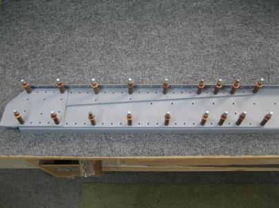
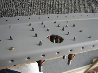
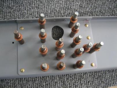
Aileron Mounting and Flap Seal

December 28, 2011

Prev | Next

Well, I have all week off this week, and due to travel, random other activities, and general stay-at-home-dad responsibilities, I only managed to start working on the airplane today, Wednesday. My original plan was to get in 40 hours on the airplane this week, but I don’t think that’s going to happen, especially since I only managed to fit in 4 hours today. Anyway, I (we) decided that I’m going to start cleaning out some of the airplane parts from our workout room. In that light, I decided it was about time to start storing the right aileron on the right wing.

So, I pulled out the aileron plans and started studying the hardware callouts.

This is for the outboard end. No spacer needed.

Here's the inboard side.

I think this is the hardware for the outboard side.

And the hardware for the inboard side, plus the AT6-058 tubing to make a spacer.

I did need to enlarge the weldment bolt holes to the proper size, so I grabbed an AN3 bolt and measured it’s diameter.

Looks like .186"

I tried a few bits and found that the proper drill bit for a AN3 bolt is a #12. Later on, I found out that the proper drill bit for an AN4 bolt is a 1/4".

One of the things I have on my list of things to do is to countersink and set the lower inboard rivets on each of the aileron hinge brackets.

At first I was kind of skeptical that you needed a flush rivet head here, given all the room in the picture…

There isn't anything even remotely close.

…but, after swinging the aileron through its full motion, I noticed that full up (trailing edge up) aileron has minimal clearance there.

Those Van's guys are smart.

Back to the hardware. One of my stocking stuffers from the girlfriend FIANCÉE was this wonderful double-drive ratcheting screwdriver that you’ve all seen on the commercials recently. I have the snap-on one, which is REALLY nice, but this one is great for fast (double drive!) fastener insertions. I’ll use the snap-on when precision counts, and the Kobalt where speed is my friend.

DOUBLE DRIVE!!!

Anyway, I used that with a socket on the end to quickly secure some of the aileron attach hardware.

I’m not sure what order these pictures are in. Here’s me cutting some of the aforementioned AT6 tubing for a spacer.

Action shot!

I don't think I got the edge of the spacer just right when deburring. I might redo this. (This was also the only place I had to make a washer substitution. I used a skinny washer to the right of the aileron attach bracket.

Here's the after shot of the outboard end.

Hey, look at that! It looks like an airplane!

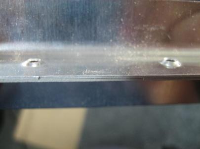
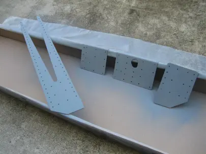
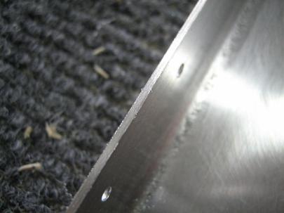
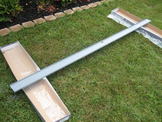
Okay, here, the ADD set in, and I needed to so something else. Time to pull out the flap seal. After edge finishing and scuffing…

Tada! Time for cleaning and priming.

Don't let the sun fool you. It was freezing out today.

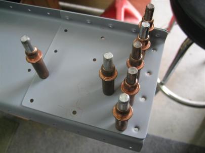
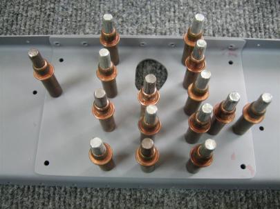
Serisouly, there pictures are way out of order. Here are my rivet counts after I was done with riveting the flap seal on.

29 total rivets set, 1 drilled out.

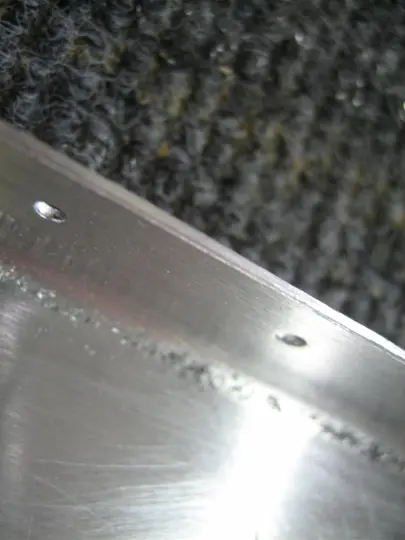
I didn’t get a good picture, but I didn’t get the rivet gun lined up right, so the edge of the set just chewed through the rivet head.

Anyway, a nice clean drill-out.

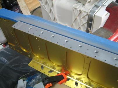
Here’s the finished product.

29 rivets closer to the end.

Next, I was trying to figure out how to line up the aileron, so instead of copying some other people’s cleco and a straight edge trick, I decided to do it by the book. Grab a straight piece of wood, drill the holes for the tooling holes in the wings, then line up the aileron with two tangential lines.

Easy enough, right?

Well, kind of. Turns out, I had used one of the tooling holes as the attachment hole for the angled bracket for the wing stands.

See? 1/4"

The upper one is still #21, though.

So, I drilled two holes at the appropriate distance for an AN3 bolt, then drew my tangential lines, then enlarged the lower one to 1/4″.

Worked well for me.

But I quickly realized that with the wing nose-down, the aileron is NOT neutrally balanced. Since there is a moment on the aileron, if I clamp it to my piece of wood, it’s going to bend the piece of wood for a false reading. Looks like I’ll have to actually construct the bellcrank and pushrod.

So, I fished out the bearing from beneath my workbenches and cleaned off the tag.

Also, I found the bellcrank attach brackets.

And cleaned off more tags.

I was trying to locate the AN3-6A bolts that are called out for the bellcrank attach brackets, and I couldn’t find them anywhere.

After about 30 minutes of build time wasted, I remembered that I had one more bag left. I thought this was just the close tolerance bolts, but alas, there were plenty of other AN bolts in there.

This bag hid from me for 30 minutes.

So then I spent about 20 minutes sorting though these bolts.

There are some AN3-6A bolts on the left there.

I have some residual confusion about bolt length, though. Here’s a known -4A and -7A.

Makes sense.

Here's the -6A. This is all good.

Oh, I guess we’re jumping around in pictures again. I’ll bring up my confusion later.

I got the brass bushing out of my storage box and deburred the edges a little.

Shiny is scotchbrited, dull is out of the box.

After inserting into the bellcrank….

Looking good, needs to be drilled to final size, though.

It just barely sticks out both ends of the bellcrank as designed.

Perfect length out of the box.

I did need to drill them out to a #21, though, for the long bolt that goes through them.

This was more difficult than I imagined it to be. I did use wood to clamp these in the vise, and lots of cutting oil for the drill bit.

So here’s where my confusion came back in. I was supposed to use an AN3-32A bolt, but when I held up the longest bolt I could find, (and after verifying that the longest bolt was the appropriate size for the assembly), I held it up to the bolt gauge thing, and it told me it was an AN3-28A. Hmm. I’ve got my three threads on the outside of the nut, so I guess I’m okay, but I’m still confused.

Anyway, now that I’ve got the bellcrank available, I need the pushrod.

Here's a closeup of the pushrod I'm going to make.

Here's the rest of the W-818 assembly.

After carefully measuring and cutting, here are my two pushrods.

One left, and one right.

After drilling two 90° #30 holes…

You can also see an AN470AD4-12 rivet.

Then, after some rivet squeezing and priming, I propped it up on my handy-dandy cleco storage units for drying.

It's like watching paint dry.

A picture of the rivet shop heads.

Oh, and one more spacer for the actual attach point for the aileron.

More spacers!

Here’s the attachment for the aileron.

This angle is weird because I've flipped the entire aileron up and around its axis.

But, after I got the pushrod installed…

Looks like an airplane!

Here’s the bellcrank area. Looks like I dripped some primer in there.

Van's tells you to prime the inside of the pushrods, too. So I poured some in there, then tried to pour it out. None came out until I installed it here, and some seeped around the edge of the pushrod fitting. Oops.

Hey, not to far off for the first try.

Within a degree or so...I'll fix this first thing tomorrow.

4 hours total today, 3 of which were on the ailerons, 1 of which was for the flap brace. 29 rivets set, one drilled out. Yahoo!

Prev | Next


Started Prepping Right Leading Edge

March 25, 2011

Prev | Next

Jeesh, I can’t seem to get a minute away from our third puppy to head outside and do any work on the airplane.

Tonight, finally, during halftime (go UNC!) and just after the game (wuhoo UNC!), I managed to go outside and do a couple things.

I didn’t want to do anything major; I really just wanted to go out there and get back up to speed. I’m kind of in the middle of rib prep on the leading edge, so I disassembled a few of the leading edge ribs and worked on what I labelled R3, or the third rib from the inboard side.

After deburring (back up, looks like I forgot to matchdrill some of the holes….sigh). Okay, after drilling, deburring, edge finishing, and scuffing, I now I have two right leading edge ribs ready for primer.

R2 and R3 (my numbering) ready for primer.

After pulling out the rest of the ribs (including the two outboard-ish ribs shown below), I went ahead and drilled pilot holes for the nutplate holes that are needed for the leading edge landing light installations. I had previously marked these while they were assembled with the leading edge using the provided template.

The two outboard ribs, now with pilot holes drilled for the bracket (the two small holes just above the lightening hole).

So here’s my thought. I really hate rib prep, so I’m basically going to do one at a time, then get it installed in the leading edge. To do that, I’ll need to prep (deburr, dimple) and prime the appropriate parts of the leading edge, and prep one additional rib. Generally, you want the surrounding structure in place for whatever you are riveting. Hence the need for the “next” rib to be clecoed in place while you are riveting a particular rib. If you don’t have the next one in place (have everything perfectly aligned), then the final structure may not be aligned. Make sense? No? Oh well.

So, I put the leading edge in my cradles and got to work with deburring. I got all the exterior holes deburred, did some edge-finishing with my permagrit block and my edge deburring tool and a scotchbrite pad, then started deburring the interior before my hand got tired.

Leading edge during some prep.

Oh, and out of laziness, I screwed the right tank loosely into position instead of taking it back upstairs. I think it’s going to be awhile before I get back to working on it.

It kind of has a funny shape with no ribs in it.

It was a short night, but got me back into the mood, so I’ll call it a success.

1 hour.

Prev | Next


Started Leading Edge Landing Lights

January 16, 2011

Prev | Next

Well, after receiving my “install only” leading edge landing light kits from Duckworks, I was kind of eager to start fiddling with something other than rib preparation.

Today, I opened up the kits and started in on adding the leading edge landing lights.

This is from my design page, where I’ve been collecting ideas for stuff (I was originally planning 2 small MR16 (2″ sized) lights in each wingtip, one taxi, and one landing):

After reading a little more, I’ve found that people who do the two lights in each wingtip dance aren’t happy with the amount of light they are getting from their landing/taxi lights. Then, I figure out they are talking about the regular halogen bulbs provided with Van’s wingtip light kit.
The people who are using the HID wingtip lights are generally very happy with the light output.

November 2010 update: After even more reading, I’ve decide that the leading edge light is really the way to go.

Now, I think I am going to put a single HID (PAR 36 style) in each leading edge for landing lights. These won’t wig-wag.

Then, I’ll use the wingtip lights for taxi/recognition, with wig-wag. I can use the smaller MR16s in the wing, and point one set wide, and one set toward the centerline. If I use regular halogen bulbs in these, I won’t have to use a warm up circuit, which is good, considering that when up at cruise and ATC calls with a traffic alert, I’ll be able to immediately start wig-wagging them for recognition. That gets rid of my need for an automatic warm up circuit (won’t be using HIDs for wig-wagging).

I’ll figure out the mechanics of the wingtips taxi lights later (single light in each wing? 2 MR16 halogens in each wing?)

Anyway, I made the decision to go with the dual landing lights in the leading edges. I plan on flying at night, and I want the most light possible.

From Duckworks, I ordered two of the round install kits, and two H3 enclosures (spot, instead of flood). I could have ordered one spot (for landing) and one flood (for taxi), but since I’m going to do something in the tips for taxi, I want both of my leading edge lights for landing.

Anyway, here are the two kits. Very obvious are the two mounting plates, the bulb retainer, the lens retainers, a bag of hardware, and the leading edge lenses.

Duckworks was kind enough to send me a spare lens. Much appreciated.

Here are the two PAR 36 style, spot enclosures for an H3 bulb. My soon-to-arrive HID kit should have H3 bulbs that will fit nicely in here. I’ll do a separate write-up for those.

I left the bag on them to prevent getting any skin oils on them.

A closeup of the H3 part of the enclosure. I had never seen one before, so this was a learning experience for me.

Also included in the kit are the instructions, an exploded view, and the templates for the cutting and drilling.

Good documentation. Well done.

Anyway, I decided to just bite the bullet and cut into the leading edges. Here is the template with the middle cut out.

Template, ready to go.

First, I cut out the rib template and used a sharpie to mark the hole locations.

Exact positioning here isn't too important because the holes in the mounting plate are huge, and you can adjust these a fair amount.

Back to the cutout, I measured the 2.5″ from the edge of the cutout to the row of rivet lines.

Special note here, I cut the paper off on the left edge of the following picture so I could leave the ribs clecoed in. This just meant I had to measure from the cutout instead of using arrows on the side.

I also measured per the plans (18.75″ from the aft edge of the top of the leading edge skin to the top part of the opening here) and taped everything in place.

Tracing with a sharpie.

Same trace, no paper.

Other wing.

Before jumping into the actual cutting, I moved on to some of the metal preparation for the other stuff. I wanted to be able to cut the leading edge openings while the primer was drying for some of these smaller parts.

Here, I’ve run a #40 bit through all of the nutplate attach holes and enlarged the middle holes to 5/32″ per the instructions.

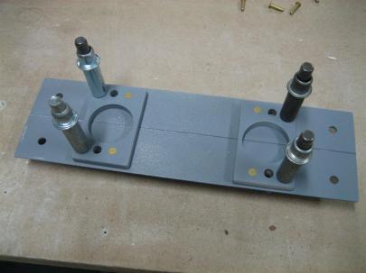
Then, I clecoed all 4 pieces together to countersink the nutplate attach holes for regular AN426 rivets. I could have used “oops” rivets here, but the lens retainers are thick enough that it wasn’t necessary.

4 lens retainers, clecoed together to give the countersink guide a good path.

I forgot to take any pictures of the rest of the prep for the lens retainers, lamp retainers, and the mounting plates. Anyway, they got prepped, cleaned, dried, and taken outside to prime.

I headed back in and got out a variety of dremel tools to cut out these openings.

There’s no turning back now.

I started near the bottom (least visible) and very far away from my line. As I gained confidence, I moved closer to my line (less finishing later).

Yikes, that's not a pretty cut.

After a little cleanup, they look a little better. Still need to do some final cleaning.

I didn’t take a picture of the other cutout, but it turned out equally as well. A lot of people really stress out about cutting these holes.

I can see where they are coming from, but I think the leading edges are great with these light openings in them. (I’m going to look like a 747 coming down final, which is exactly what I want (visibility and recognition).)

Pretty leading edges. (Oh, and this was the first time in a long time I've been able to work with the garage open. It was almost 40°F today!)

Okay, back to the primed parts. I had the urge to set some rivets today, and I nailed all of them. I finally feel like I’m starting to get into a groove (although squeezing really isn’t that hard.)

Here, I’ve clecoed the provided nutplates to the lens retainers.

Ready to start some riveting.

A closeup of some AN426AD3-3.5 rivets.

24 rivets set (beautifully).

Equally beautiful shop heads.

8 more rivets set (I did use "oops" rivets here).

More shop heads.

I got out one of the bulbs and just placed it in the mount just for kicks.

Looks like it will fit.

Found the screws and actually screwed them in. These things are going to look awesome.

Finally, I found all the pan-head screws and lightly screwed them in place.

Sweet.

I don’t think I’ll do any further painting of these. I like the primer grey.

I’ll do some more on the landing lights soon, but for now, I need to get back to rib prep. Hopefully this week I’ll have a writeup of the HID kit that arrives.

3.5 hours, 32 rivets. Wuhoo!

Prev | Next


Leading Edge/Tank Cradle, Right Tiedown Bracket

September 28, 2010

Prev | Next

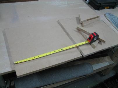
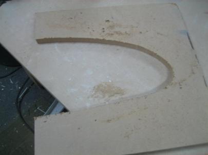
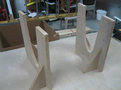
A few days ago I had the circular saw out, and I saw (pun intended) a 16″ wide piece of 3/4″ MDF sitting around, so I took a quick look at the plans, and decided that 16″ x 16″ might be a good starting point for the leading edge/tank assembly cradle.

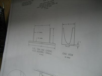
The plans (second picture down) show 13″ x 15″, but I’ve heard that some people break the cradle at the thinnest point.

Anyway, it took me all of 30 seconds to cut the 2 big square pieces and the four triangular pieces also pictured.

Tonight, I pulled those out for assembly (a quick night in the shop).

16" x 16" cradle walls, with 4 triangular supports.

Van's wants you to mount them on a 36" long 2x4, but I decided to go another route. Read on.

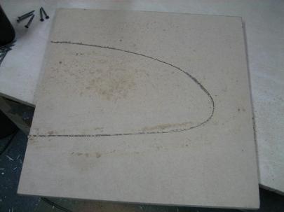
I used a thick magic marker to offest from a tank rib (room for pipe-insulation to protect the skins).

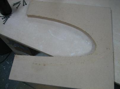
After the cut.

Tada!

After the cut. (Déjà vu)

Tada! (Déjà vu)

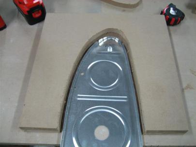
After both were cut out with the jigsaw, I laid (layed? Em, help me out here) the tank rib into the cutout to make sure I had offset the cuts enough.

Looks good to me.

So, here’s an expplanation of my “alternate route”.

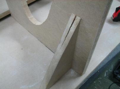
Because Van’s specifically states that this just helps in assembly, and is not an alignment jig, I decided I didn’t really need to take up a lot of space with a 3 foot wide cradle that would undoubtedly get in the way. Instead, I am making the two halves of the cradle independently, and will use them (approximately 3 feet apart). I also figured they would be stable enough with one of these triangular pieces on each side, which they were.

I predrilled the cradle, but not the gusset, and it cracked as I assembled with some coarse-thread drywall screws. Bummer (I never thought I would put a picture of my crack on the internet.)

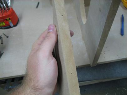
For the other ones, I pre-drilled the gusset, too.

After everything was all said and done, I am pretty happy with them (damn crack!).

I need to grab some pipe insulation to protect the skins.

Best part, they nest nicely for storage before (and after) use.

Then, I looked around for something I could get done with the half hour of attention and “eyelids-open” time I felt I had left.

I shot a quick coat of primer on the right tiedown bracket (and spacers), and then waited for the first sides to dry before flipping them over and hitting the other side.

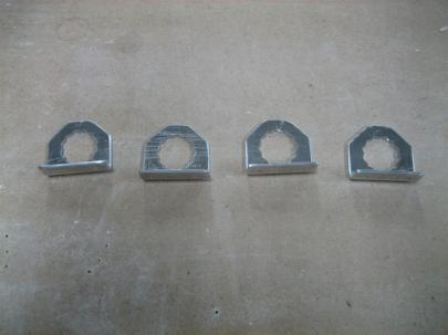
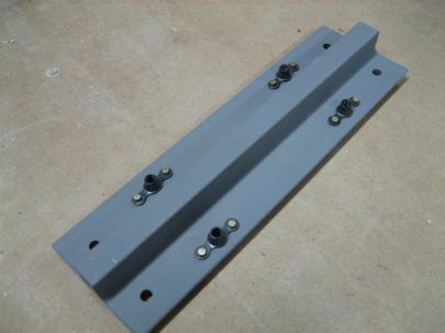
While the whole thing dried, I needed something else to do, so I grabbed the  T-715 Anti-Rotation brackets (which come all connected like the old plastic models used to. Remember you had to use a pocket knife to cut off the little tabs after bending and twisting one model piece from the rest of the pieces.)

Anyway, after getting them apart, I edge finished all four on the scotchbrite wheel. Maybe 10 minutes, and for the record, I am going to log this time under Spars, because I’m waiting for the tiedown brackets to dry. I don’t feel like adding an entry under tanks just yet.

When it is years and years from now, and you ask me how my hours it took me to finish my tanks, and I say “xx hours,” remember to add 10 minutes to that to get the real answer.

Edge finished anti-rotation brackets. (How do I edge-finish the inside edges of these? Hmm.)

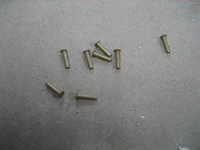
Okay, now that the tiedown bracket is dry, let’s find those AN426AD3-7s – HOLY CRAP THESE THINGS ARE LOOOONG!

Whoa. Long rivets.

4 of 8 rivets set (squeezed).

Tada! (That's three "tada"s today. Aren't you lucky!?) Don't forget the nutplates on the other side. I almost did.

Oh, and by the way. Don’t prime and then wait 10 minutes for things to dry, the primer really hasn’t cured, and it will scrape off with a fingernail. After waiting 24 hours, or better yet, a few days, this stuff gets rock solid. I need to remember that.

I shot another coat on these after they were riveted. I was too ashamed of the first coat to take a picture. Sorry.

8 rivets and 1 hour. 0.5 in “Wing” and 0.5 in “Spars.” (I’ll put the log in both places. We’ll see how that works.)

Prev | Next


Primed and Started Riveting Right Rear Spar

September 12, 2010

Prev | Next

Well, after a $15 stop at Napa ($10 for primer, $5 for sensor-safe RTV), I got back to work on the rear spar.

I spent a lot of time just kind of staring at everything today. The instructions are careful to point out that at the inboard part of the spar (where the reinforcement fork is), you can’t reach the spar flange holes with dimple dies for later dimpling, so you should do it now.

With that in mind, I wanted to make sure I got everywhere that may need dimpling later, so I also dimpled above the two (middle and outboard) doublers. You can see in this picture (the middle doubler) where I decided it would be a good idea to dimple (drill, deburr, then dimple, of course) the flange holes. I did this for both the spar and the doubler plates, which also have flanges on them.

The middle spar area, shown after drilling, deburring, and dimpling the flange area.

Same thing here. Also, I dimpled the 4 outboard holes (instead of countersinking), per previously approved builders who have talked to Van's.

I got back to thinking about the tank dimple dies, and whether they were really helping with skin-to-structure attachments. The idea is the the tank dies (which are deeper to account for pro-seal while riveting the tanks), when used on the skeleton, allow the regular dimple in the skin to sit better once riveted.

I got out some scrap, dimpled the “skin” with regular dies, and dimpled the “skeleton” with one tank and one regular die.

You can see on the left, those are the regular dies. The ones on the right is a regular die sitting in a deeper tank dimple. The tank dimples didn’t help anything sit better, because they were both fine.

A little blurry, but the "skin" sat equally well for both set of dimples.

The tank (deeper) dimple is on the right. You can see I'm not having any "seating" issues on the left.

Anyway, I think I am going to go back to using the regular dies on everything. Enough about that, though, let’s prime!

The rear spar components, getting primed after some more edge finishing, washing, drying, and positioning in my wood floors boxes.

Also, I went back and masked off the spar where I had countersunk.

Some of the nutplate attach rivets are not as flush as I would like them to be. I may get a rivet shaver and shave some of these down and reprime. We'll see how the tank skin sits on them.

Back on the rear spar, I posted a couple pictures of my edge finishing procedure. First, use the Permagrit block to smooth out the tooling marks. This picture is the resulting burrs that need to be deburred.

The permagrit is great, but it does leave some pretty decent sharp edges.

Then I used my “v” deburring tool to knock off the 45°.

After this, I usually use a scotchbrite pad to smooth everything out.

After blowing the aluminum dust off with shop air and a good wipe-down with MEK, I took the spar outside so I could paint the grass with my overspray.

I think this is the second side. Only one bug landed on my spar. I left him there for now. (He may be my first passenger.)

After a few hours, I returned out to the garage (workshop/mancave) to do some riveting.

First step: Ignore Van’s suggestions to tape off all of the holes that don’t get riveted now. (I know the warning bells must be going off right now, but it all worked out fine. Just have to read the plans carefully.

I left clecos in all of the “do not rivet now” holes. 6 regular AN470AD4-4 rivets on the left, and some AN426AD4-4 (I think) rivets in the dimples on the right.

SEP 14 UPDATE: WHOA! Those 4 on the right can’t be set now, because the W-712 outboard rib will get riveted to these holes, too. Glad I didn’t get to happy with the rivet squeezer.

These 10 can be riveted now. (Sep 14, 2010 Update: Nope. Just the 6 on the left can be set now.)

Same exercise here. Only 5 rivets can be set now.

I didn't really mark anything here, because I didn't really start on riveting the fork on yet. Next post, I'll be very careful about what to rivet.

Then, I actually started riveting. I love my new Cleveland Main Squeeze. Squeezing these An470AD4- rivets is so easy now.

Here are the 5 shop heads from the middle of the rear spar.

The same 5 from the manufactured side.

Oh, and I did 6 more at the W-707F doubler plate, but forgot to take pictures. 11 total. Also, I was mixing this and house projects over the course of a few hours, so I’m going to estimate it was about 2.0 hours today.

Prev | Next


More work on the Counterbalance Skin

July 20, 2010

Prev | Next

Things have been slow with the airplane recently, right? Well, after a few weeks of letting the garage slowly spiral into a mess of hall closet items (while I’m redoing the floors), saw dust (while I’m redoing the floors), and aluminum dust/shavings (I am working on the plane a little), I decided it was time to get things cleaned up. After an hour of cleaning and organization, I snapped this picture of a nice clean workbench and floor area. Doesn’t really do it justice, but something about a clean workbench makes me happy (notice how I am not showing you a picture of my second workbench!)

(Don't tell the girlfriend I had the vacuum cleaner up on the table going back and forth. It works pretty well, but I accept no blame if you try this at home.)

Okay, finally on to the project. My replacement E-713 came the other day. instead of trying to cleco it on to the already-dimpled skeleton and matchdrill, I am going to trust Vans’ pre-punches and just run a #40 bit through the appropriate holes before deburring and dimpling.

After that was complete, I taped the outside of the skin that I want to protect from primer and scuffed everything up.

Ready to prime...almost. I'm still waiting on a #10 dimple die from Avery. Should be here any day.

Because this part of the exterior side is under the main left elevator skin, I'm going to prime it. Those two smaller holes need to be drilled to #28 before dimpled for #6 screws.

After that, I grabbed my two trim tab horns, and deburred, scuffed, and dimpled the flange holes.

I still need to trim these down per the plans for the electric elevator trim, but I also haven't ordered my electric elevator trim kit yet.

Finally, I disassembled the trim tab to get a little start on that. Here’s the spar, deburred, scuffed, and dimpled on the bottom flange.

The top flange (on the left side of the picture) needs to be countersunk for the upper trim tab skin, because the hinge sits just below the flange, and can't accept a dimpled flange.

2 hours in the shop today, but only 1 hour counts as build time. Hooray clean shop!

Prev | Next


Started Prepping Left Elevator Skeleton

July 2, 2010

Prev | Next

Even though it was my day off, I spent the day trying not to get stung by bees (mowing the forest behind my fence) and meeting the girlfriend for food. After that, I managed to waste an hour or so installing a fan in the garage. Recently, it’s been brutal in the garage, so this morning, while I was walking around Lowe’s, I saw a small ceiling fan for $17. I couldn’t say no. It was harder to install than our nicer fans inside (no little quick-disconnect fan blades or anything), but in the end, it makes me cooler in the garage (double meaning intended).

Huzzah!

Okay, back to work. I think you guys might have seen this picture yesterday, but here it is again…the little riblet I made after drilling.

Looks good. I am proud of this little guy.

Then, I moved over to the spar. These four holes get countersunk because they attach E-705, but the elevator horn has to sit over the rivets but still flush against the forward face of the web.

Beautiful countersinks.

While I had the countersink cage set up, I pulled the trim tab spar out of the elevator and started on it.

Countersink the top flange, dimple the bottom flange.

Aren't these countersinks nice?

After countersinking, both the tab spar and the left elevator main spar were scuffed (more), edge-finished, and then got a trip inside to the sink for a quick rinse before coming back outside to eventually get a coat of primer.

I'm getting close to riveting something, watch out!

Anyway, two very productive hours, and I think I can rivet some reinforcement plates tomorrow if I want. Wuhoo!

Prev | Next


Primed the rest of the Left Elevator Stiffeners

May 31, 2010

Prev | Next

Tonight, I moved on with the left elevator by matchdrilling the upper stiffeners.

Here are the upper left elevator stiffeners, after trimming, being matchdrilled to the skin. First, I drilled and clecoed the forwardmost hole.

The three forwardmost holes clecoed.

After finishing, I traced the stiffener outlines on the inside and outside of the skin.

These will help me devinyl later.

You can see I have already done the lower surface of the elevator (it's upside-down on the table).

And, of course, since I forgot to add RTV to the right elevator (still trying to figure out a way to get some RTV in there), I wrote a little reminder on the inside of the left elevator.

Hopefully I'll see this as I pull out the last of the blue vinyl just before assembly.

Next, devinyl along the traced lines and then deburr and scuff.

Left elevator skin interior after devinyling, deburring, and scuffing.

Next up, I deburred and scuffed the remaining stiffeners. (I don’t have any pictures, but after this, they got dimpled and then primed.)

Because the upper surface doesn't have the trim reinforcement plate, there are 4 (instead of 3) of the short stiffeners.

Next up, devinyl and deburr the outside of the skin.

Skin devinyling.

A small tip here. I decided that at the aft end of the elevator, i would leave a little blue vinyl instead of connecting the upper and lower surface bare spots. This way, If I need to rest the elevator on its trailing edge, I won't be damaging the finish on the trailing edge.

Because it was late, I couldn’t use the c-frame.

Instead, I grabbed the hand squeezers and dimpled anything I could reach.

Just for kicks, I held up the trim reinforcement plate (and cover, still covered in blue vinyl) which will be riveted underneath the skin to the right.

Here are the other sides of the upper stiffeners getting primed.

I toook these inside for a good washing with Dawn before drying them, wiping with MEK, drying some more, and then shooting with primer.

I had a few more minutes, so I started match-drilling the skeleton. Here is one of the spar reinforcement plates being drilled to the spar.
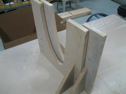
I used my 12" #30 bit due to cleco-clearance issues.

Finally, before heading in, I shot a coat of primer on the other side of the upper left elevator stiffeners.

Nighty-night.

Prev | Next