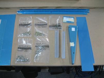
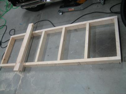
Leading Edge/Tank Cradle, Right Tiedown Bracket

September 28, 2010

Prev | Next

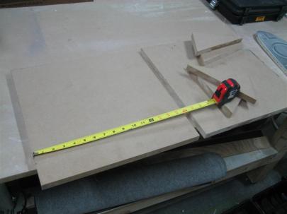
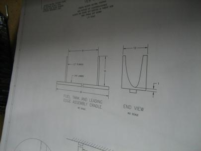
A few days ago I had the circular saw out, and I saw (pun intended) a 16″ wide piece of 3/4″ MDF sitting around, so I took a quick look at the plans, and decided that 16″ x 16″ might be a good starting point for the leading edge/tank assembly cradle.

The plans (second picture down) show 13″ x 15″, but I’ve heard that some people break the cradle at the thinnest point.

Anyway, it took me all of 30 seconds to cut the 2 big square pieces and the four triangular pieces also pictured.

Tonight, I pulled those out for assembly (a quick night in the shop).

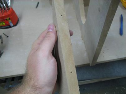
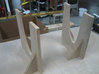
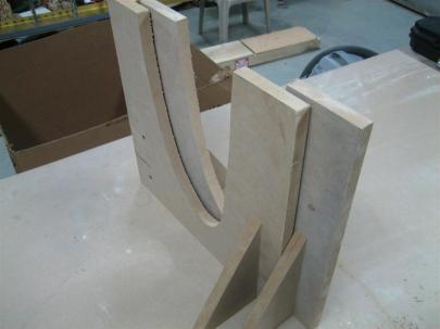
16" x 16" cradle walls, with 4 triangular supports.

Van's wants you to mount them on a 36" long 2x4, but I decided to go another route. Read on.

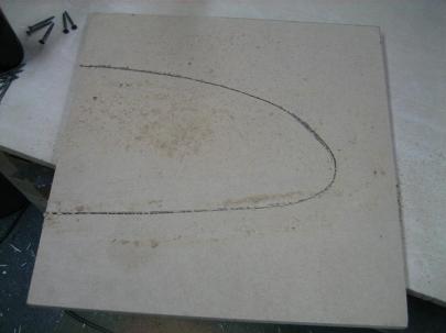
I used a thick magic marker to offest from a tank rib (room for pipe-insulation to protect the skins).

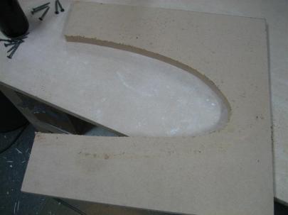
After the cut.

Tada!

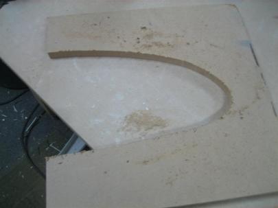
After the cut. (Déjà vu)

Tada! (Déjà vu)

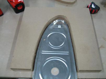
After both were cut out with the jigsaw, I laid (layed? Em, help me out here) the tank rib into the cutout to make sure I had offset the cuts enough.

Looks good to me.

So, here’s an expplanation of my “alternate route”.

Because Van’s specifically states that this just helps in assembly, and is not an alignment jig, I decided I didn’t really need to take up a lot of space with a 3 foot wide cradle that would undoubtedly get in the way. Instead, I am making the two halves of the cradle independently, and will use them (approximately 3 feet apart). I also figured they would be stable enough with one of these triangular pieces on each side, which they were.
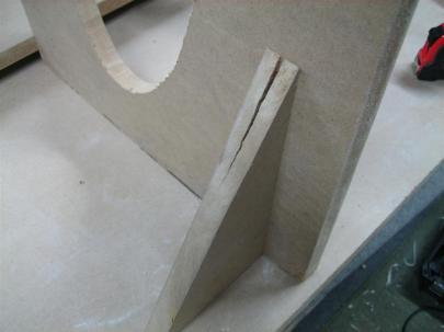
I predrilled the cradle, but not the gusset, and it cracked as I assembled with some coarse-thread drywall screws. Bummer (I never thought I would put a picture of my crack on the internet.)

For the other ones, I pre-drilled the gusset, too.

After everything was all said and done, I am pretty happy with them (damn crack!).

I need to grab some pipe insulation to protect the skins.

Best part, they nest nicely for storage before (and after) use.

Then, I looked around for something I could get done with the half hour of attention and “eyelids-open” time I felt I had left.

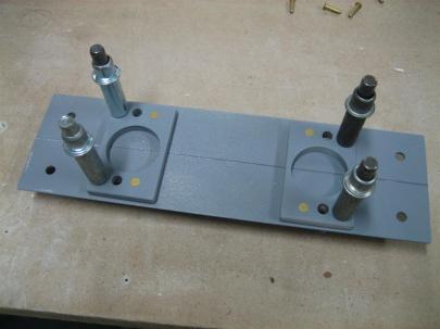
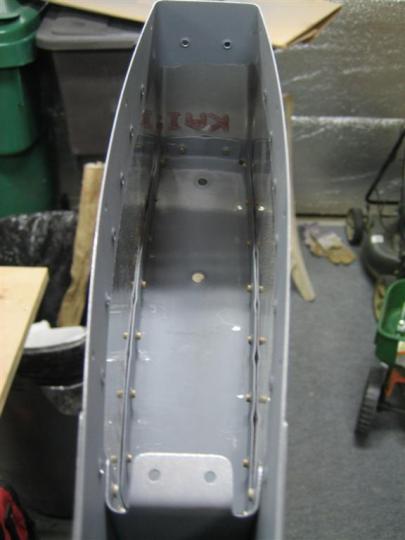
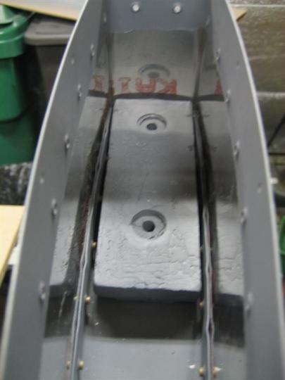
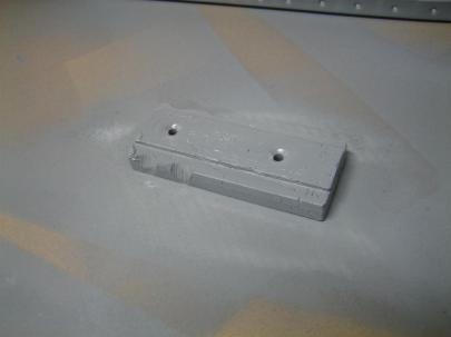
I shot a quick coat of primer on the right tiedown bracket (and spacers), and then waited for the first sides to dry before flipping them over and hitting the other side.

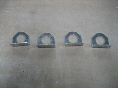
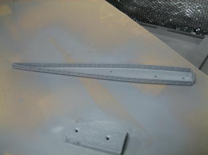
While the whole thing dried, I needed something else to do, so I grabbed the  T-715 Anti-Rotation brackets (which come all connected like the old plastic models used to. Remember you had to use a pocket knife to cut off the little tabs after bending and twisting one model piece from the rest of the pieces.)

Anyway, after getting them apart, I edge finished all four on the scotchbrite wheel. Maybe 10 minutes, and for the record, I am going to log this time under Spars, because I’m waiting for the tiedown brackets to dry. I don’t feel like adding an entry under tanks just yet.

When it is years and years from now, and you ask me how my hours it took me to finish my tanks, and I say “xx hours,” remember to add 10 minutes to that to get the real answer.

Edge finished anti-rotation brackets. (How do I edge-finish the inside edges of these? Hmm.)

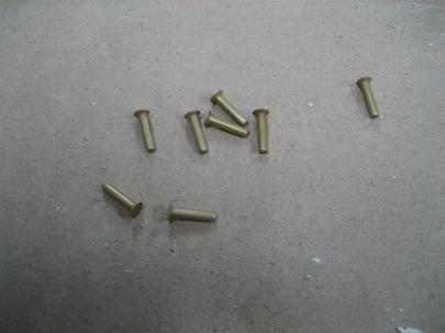
Okay, now that the tiedown bracket is dry, let’s find those AN426AD3-7s – HOLY CRAP THESE THINGS ARE LOOOONG!
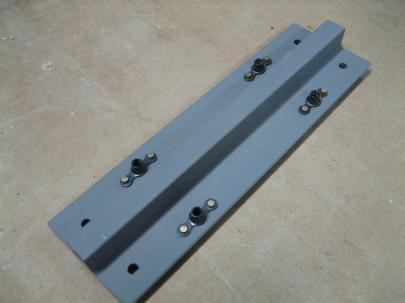
Whoa. Long rivets.

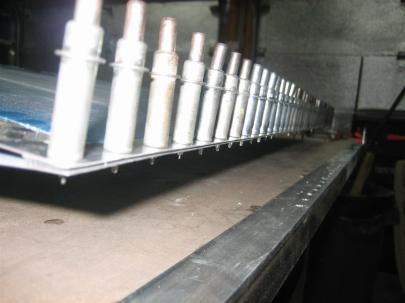
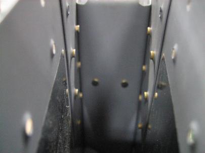
4 of 8 rivets set (squeezed).

Tada! (That's three "tada"s today. Aren't you lucky!?) Don't forget the nutplates on the other side. I almost did.

Oh, and by the way. Don’t prime and then wait 10 minutes for things to dry, the primer really hasn’t cured, and it will scrape off with a fingernail. After waiting 24 hours, or better yet, a few days, this stuff gets rock solid. I need to remember that.

I shot another coat on these after they were riveted. I was too ashamed of the first coat to take a picture. Sorry.

8 rivets and 1 hour. 0.5 in “Wing” and 0.5 in “Spars.” (I’ll put the log in both places. We’ll see how that works.)
Prev | Next


Left Elevator Stiffeners, Part Uno

May 26, 2010

Prev | Next

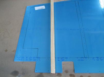
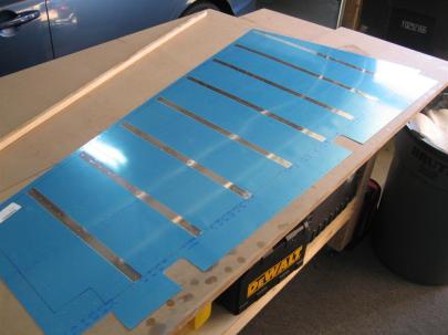
Another quick night in the shop. First thing, I fired up my 6″ grinder (with a scotchbrite wheel attached) and edge-finished half of the stiffeners. After that (about 45 minutes of the total 1 hour in the shop), I started the stiffener to skin drilling dance.) In this first picture, I’ve just placed the elevator trim backing plate in plate for the effect. On the right, my first two holes drilled (into a sacrificial piece of MDF) on the bottom of the left elevator.

Bottom of the left elevator, working from inboard to outboard.

Here are three of the shorter stiffeners drilled, and the forward most hole on the last four drilled.

3 done, 4 to go.

All of them drilled.

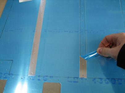
Next, I uncleco the assembly from the table, and recleco just the front and back holes of the stiffener so I can flip the skin over to match-drill the last hole (it’s prepunched in the skin, but not the stiffener on a couple of the stiffeners). Then, I traced around the stiffeners with a sharpie, then pulled them off and clecoed them to the outside of the skin, again, to trace them with a sharpie. This will help me figure out where to remove the blue vinyl later instead of just guessing (like I did with the right elevator.

Of course, the stiffeners don't go on the outside of the skins, I am using them to mark the outside of the skin for devinyling.

See? All traced.

The inside, too.

lastly, I removed the stiffeners and marked them before prep for priming.

B2 is upside labelled upside-down. Maybe I should remake the stiffener. /sarcasm off.

One boring hour today.

Prev | Next


First of Many New Garage Shelves

May 16, 2010

Prev | Next

So.

The front wall of my garage is a little chaotic. I have an old armoire (whoa, I had to go to wikipedia to figure out how to spell this) out there holding some airplane things, and then a set of collapsible shelves that basically hold small things that don’t hang on the walls (pegboard) easily.

I need to get a little more organized, but I’m limited because of the 45° support holding up my overhead shelves.

Workbench Construction 010

This was an early picture, without the other shelving unit.

Anyway, I want to push any newly-constructed shelves back against the wall, so unless I want to limit myself to 5 feet tall (no!), I need to limit the width to about 28 inches.

I’m going to use the same construction technique as the two workbenches (here and here) I built. Here’s the plan:

Here's the concept. 6 feet tall, 28 inches wide. Various heights for the shelves.

First up, cut some wood!

The ones on the left are the left-to-right supports, the shorter ones on the left are the forward-and-aft supports.

Then, I took the long ones and the short ones and mocked them up in this little jig (for squareness) before drilling.

My drilling and assembly jig.

Then, for some reason, I took a picture of the wall.

The wall. No more description needed.

Then, like the airplane, I decided to drill pilot holes first.

I believe the drill bit on the left is 1/8".

Then, I started assembly.

Here's the first shelf complete. (And my Dewalt circular saw.)

Two of six.

Oops, I stopped taking pictures of the assembly.

After the frame was complete, I attached some non-locking wheels to the bottom.

Finally a couple days later, I started loading the thing up (will be organized and labelled later) and snapped this picture.

It looks crooked in the picture, but it really isn't. And yes, that is (expensive) MDF for shelves. It just seemed like the right thing to do.

I went with (from top to bottom) a 12″ inch shelf, then two 6″ shelves, then another 12″ shelf, then an 18″ shelf.

The idea is that I build 5 more of these (for each of the areas between those 45° supports to vastly increase my storage space in the garage. Also, they are not attached to anything, so I am going to wheel them onto the moving truck in a few years if I decide to move.

What do you guys think?

Prev | Next


More Trailing Edge Work

March 28, 2010

Prev | Next

After last night’s bad fitting trailing edge, I decided to mark where the dimples weren’t sitting properly, and enlarge the countersink ever so slightly.

The problem is that if you make the countersink large enough to accept the dimple perfectly, you create a knife-edge on the wedge. I guess that is why they have you use the aluminum as a drill guide for the countersink bit. After deburring the few knife edges that I got, it ended up working pretty well, but some of the holes are enlarged a little. With the pro-seal and the double-flush rivets, I am not too worried, but it still bugged me a little. It appears other builders have run into this issue as well.

Another shot of the not so good trailing edge before enlarging the countersinks.

Before I thought I would be able to tackle the rest of the trailing edge today, I got some of the “not-reachable-with-the-squeezer” rivets. here’s a shot of some shop heads for the counterbalance skin to skin rivets.

Decent shop heads.

I also finished up the rivets for the counterbalance rib.

More shop heads.

Then, I installed and removed the counterbalance enough to be able to file away some weight so the lead cleared the shop heads of the interfering rivets.

Nice tight fit today.

Here's the counterbalance. The best file for this left big cutouts, so don't judge me for these.

I also finished dimpling the tip rib and got it edge-finished, cleaned, and primed.

Waiting for primer to dry is like watching a pot of water boil. I can't complain though. It's dry to the touch in about 15 minutes.

Even though that was plenty of work for the day, I decided to tackle the trailing edge. I had everything I needed (Lowe’s didn’t have any RTV, but then I remembered I had some at home from my motorcycle habit, so I was in luck).

Here's me attempting to design a way to keep the trailing edges apart. This sucked, and I ended up using scrap 2x4 in between the stiffeners.

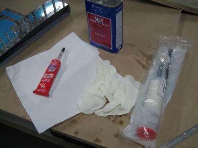
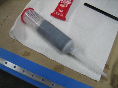
Here’s my tools. RTV, MEK, gloves (I used about 8 pairs) and the tank sealant.

Tools.

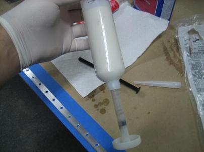
Don the gloves, and get ready to mix. I had to read the directions about 15 times before I understood. The hardener (I think) is in the tube part of the plunger. You stick the black piece (behind the big tube) into the hole in the plunger, and as you push the plunger from the bottom to the top, you push the black part so the hardener in the plunger is expelled into the larger tube. Confused yet?

Ready to mix. (I've already cleaned all of the parts.

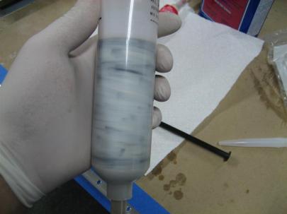
After pushing the black piece (back on the table now) up to start the mixing process, you twist the plunger head while moving up and down, which starts to mix.

This is after about 75 strokes, which is what the directions say you have to do. I had to keep going. (I may have been doing something wrong, I don't know.) I kept going after this to get a more uniform "black death" color.

Then you unscrew the plunger shaft and screw in the nozzle. Okay, where is my caulking gun? I don’t have a caulking gun. OH MY GOD I FORGOT A CAULKING GUN.

Here it is fully mixed.

That’s okay, I just stuck the handle of a large screwdriver down the tube and it worked great.

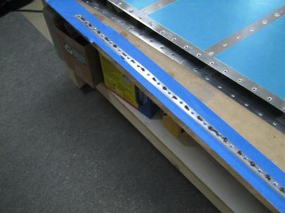
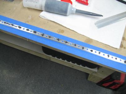
Here's one side, ready to be spread out. I put a dab between each hole, and then used a scrap piece of aluminum to spread it out nice and evenly.

Another shot. This seemed to be an appropriate amount of sealer.

After that step, things started getting messy, and I had to change gloves a lot (it gets everywhere), so I stopped taking pictures. After I got both sides covered, I laid it into the scuffed and cleaned trailing edge area of the skin.

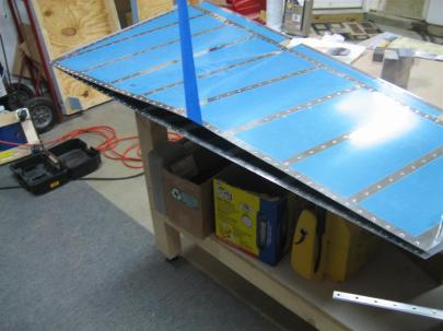
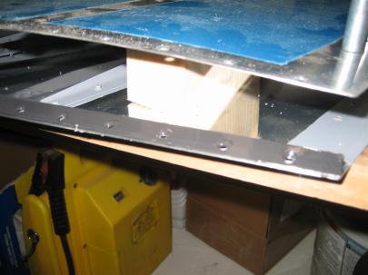
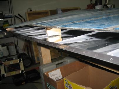
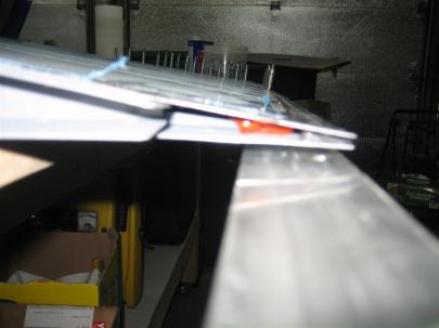
Look how good that looks. (Also, you can see my 2x4 spacers.)

Another shot.

Of course, I did a marvelous job putting a perfectly penny sized glob of RTV on the last (aft rivet) of the stiffeners before I removed the wood spacers and closed up. (The wood spacer near the bottom of the rudder was a pain in my ass. I lifted up the trailing edge a little with the top skin, so it stopped squeezing the block, and of course the block slid down toward the front of the rudder. Of course now I can’t let go, but I’m too far away from the other workbench to reach all of my long-reach tools. Ever see one of those situations where a guy has one foot in a boat and one foot on the dock, and he’s stretching and stretching? That was me. Except I finally reached a BFS (big freaking screwdriver) and managed to get the block out without contaminating any tank sealant or RTV.

Here's a blurry shot of the bottom RTV glob. Glob is a technical term.

Then, I got the rudder clecoed to the angle, wiped off any excess sealant, and moved the hole thing to the top shelf of my workbench.

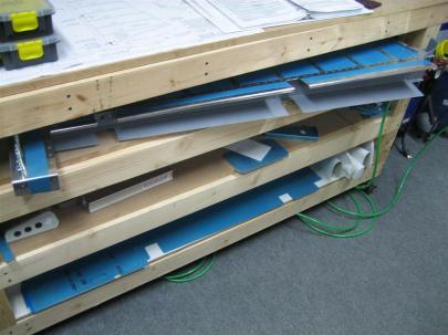
Storage, kind of. I'm going to leave this for a whole week while I start on the elevators.

I think it was 11 rivets.  2 hours before the trailing edge, one hour for the trailing edge. The next post is still from today, but I am tracking it in another section and in another column for total time, so it’s getting its own post.

Prev | Next


More Rudder Stiffeners

February 20, 2010

Prev | Next

After a very busy end of the work week, I managed to squeeze a couple hours of airplane time in the shop today. I started by mocking up the R-902 front spar, and drawing a black line on the left rudder skin (this is the forward bottom edge of the left skin). I’m going to draw out all of the mating surfaces on these skins, since they will have to be primed at different times (more on this later).

Forward bottom corner of the left skin. You can see the front end of the only full size stiffener.

Next, I dove into match-drilling the stiffeners and skin. Here are the first size holes drilled. I don’t want any waviness in the rudder, so I am clecoing every hole as I drill. (You can see that like everyone else, I am drilling straight into the MDF that’s on top of my workbench. This works well, and is basically per the plans.

First six holes of the stiffener to skin match-drilling process.

After I finished the first (lower) stiffener, the next one needed to be cut down to size. I made another mark on that stiffener, this time in line with the front spar line I drew earlier. Now, when I trim the stiffeners on the aft side of that line, there will be no interference with the front spar.
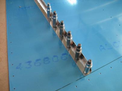
Getting ready to trim the second stiffener.

Then, I got in the groove, so the next picture was after a few of the stiffeners. I used my cordless for this. Not as noisy.

Lower 4 stiffeners done on the left skin.

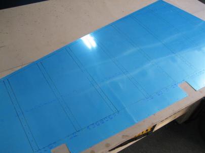
All done with the left side. Oh yeah, it was 60° today, so I worked with the garage door open. So nice…

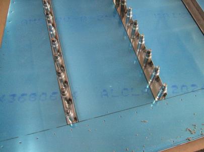
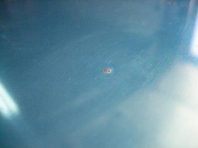
There's something really rewarding about getting to this point. OH MY GOD!, WHAT IS THAT MARK BETWEEN THE FIRST TWO STIFFENERS!?

A closer look…

AHHHHHHHHHHHHHHH!

I turns out I dropped my cleco pliers from about 8 inches right after I completed the first stiffener. Instead of immediately pulling up the stiffener to inspect the exterior skin, I guessed that it was going to be salvageable and pressed on.

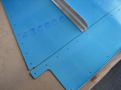
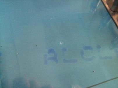
To put it into context, it is just above the first "L" in "ALCLAD."

It’s not that bad, but it would be very noticeable If I polish. (Even if I paint, it is still a pretty big mark.

From the other (exterior) side. Bummer.

Anyway, I’ve heard people talking about using the back of a spoon to gently massage stuff like this out. I spent about 15 minutes gently massaging, and I ended up with this. It looks worse than the original picture, but it is pretty flush now, and I think with a little more work may even go away.

After massaging. It's good, but not great.

Anyway, after that fiasco, I laid out the right skin, marked the front spar and trailing edge wedge on the skin, and started match-drilling stiffeners. I was in such a groove that I forgot to take a picture when I had all of the stiffeners drilled and clecoed. (I didn’t forget to take a moment to admire it, I just forgot to share it with you.)

After removing most of the clecos post match-drilling.

Also, while all the stiffeners were in place, I drew lines on each side of the stiffeners so I would have a guide for devinyling.
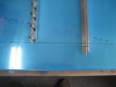
I call it match-drawing.

After pondering my next few steps (debur, dimple, scuff, clean, prime, backrivet the stiffeners on), I decided I need to get the vinyl off for deburring.
Here's the wooden stick I use as a guide for the soldering iron.

I don’t think I’ve shown you guys my round-tipped soldering iron yet. Here you go.

Soldering iron, heating up.

After running the soldering iron down the pre-drawn lines, I get to devinyl. I say “get to” because I like this part.

Whose fingers are those?

All done with the stiffener devinyling. You can see I didn’t do all of the outlined parts, because I want to prep and prime those later. (Have to assemble the skeleton, cleco on the skin, and match drill before you can debur, dimple, prep, etc. the rest of the stuff. Also, I need to find out if people are priming the trailing edge area before using Pro-seal. I have a feeling people are just scuffing, but I’ll ask the forums to make sure.

Ready to deburr, dimple, scuff, and prime.

Next up, devinyling the left skin.

2.0 hours today. Gotta go get cleaned up for festivities tonight.

Prev | Next


Started Rudder – Stiffeners

February 16, 2010

Prev | Next

Well, with the vertical stabilizer safely in the airplane storage room, it’s time to get started on another part. Next up, the (infamous) rudder. There are a lot of steps on the rudder that give a lot of builders a lot of trouble. I am confident, but will continue to use other sites on a daily basis before doing any work that evening. That’s worked out well for me so far, so I’m going to keep at it.

First thing’s first, the ceremonial plans change. I still keep the plans on my second workbench. Maybe someday I’ll find a place to actually hang them up.

Drawing 7. The Rudder. (Cue dramatic music.)

I spent a little time trying to figure out whether I will do the stiffener-to-skin dance on both sides at once, or just one side. You can see below that if I had another longer piece of MDF and maybe took my vise off the bench, I could set the skins on opposite corners and maybe do them at once, but I think I’ll just do one at a time, making sure I can reuse the holes I plan to drill into the table. (Drilling, and then clecoing, the stiffeners to the skins all the way into the table will allow me to keep everything very steady. Sounds like a good plan to me, and is pretty much standard given that Van’s suggests doing so in the construction manual.)
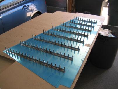
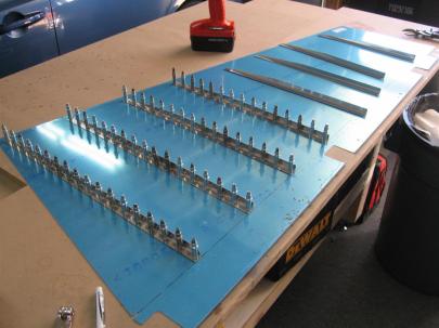
I'll have to do one skin at a time. I don't want to get too crowded, and I am not overly concerned with building efficiency.

First step in the manual is to start on the stiffeners. I fished out the bundle of stiffeners (there are two bundles, one set for the rudder, and one set for the elevator) and studied the plans.  For the back side of the stiffeners (with the shallow angle on the right side of the picture below), these are the final cuts, so I need to be careful. For the front side (you can see a little of the front of a stiffener on the left in this picture), only 2 of the 16 stiffeners will be to full length, so the other 14 can be rough cut until I can mark them to final size per the note at the tot of this picture.

Stiffener Trim detail, drawing 7.

Next, I headed inside to sit myself down at the table so I could watch the UNC vs. GT game. I know some of you are panicking right now, but please calm yourselves. While it appears that my winerack is empty (OH MY GOD, NOOOOO!), that is really our third winerack. Rest assured that our two primary wineracks are stocked satisfactorily.

Is that an empty winerack? Don't worry, the hooch is stored in another rack.

Anyway, here’s the stiffener bundle I’m about to break open.

R-915. (I can't think of a funny caption this morning, so all you get is the part number.)

I broke open the bundle and started snipping from center hole to center hole. After a few stiffeners, I started biasing the cuts to the sides of the holes, but only where I was sure that I was going to have to remove more metal later.  Here you can see that on the top part of the cut, I’m lined up with the left side of the slot.

Snip snip.

I included another picture of the angle cut for the front end of the stiffener. Remember, only two of these cuts are for real, as the next step is to chop off varying lengths of stiffener from the front to match up with the pre-drilled holes in the skin.

Snippity Snip snip.

Here’s a rough cut for the front end. See how I am going to have to remove more metal because of the notches. Might as well get closer on the first cut. That’s why I started biasing the cuts to one side after the first few.

The front end of the first stiffener.

First 8 front ends done.

Yikes, those are going to need some edge finishing.

All 16 stiffeners’ front ends done.

That's a spicy stiffener.

Next, I used an admittedly fat sharpie to draw the required cut lines on the aft ends of each of the stiffeners.

Lines drawn, back to snipping.

And here I am using the snips to cut that longer line. Snips aren’t perfect for this task, since they bend the metal, but if you work them correctly, they will only bend the piece you are cutting off. There is kind of a rocking motion you have to feel with each cut. You’ll get it when you try.

Snipping the aft end.

Here’s the first one, done.

I'm a little camera happy today, don't you think?

Then, I finished up the other 15, and was left with these scraps. If I had even the slightest hint of an artistic bone in my body, I would make some comment about how these resulting spirals are king of cool. But I don’t, so I won’t.

Scrap from the latest cuts.

All 16, ready to be devinyled.

Done with those cuts.

Starting to devinyl…

This is going to take forever.

I’m glad I did the devinyling inside. When the vinyl is warm, it comes right off.

Holy crap that's a lot of blue v-......WHOSE TOES ARE THOSE AND HOW DID THEY GET IN THE PICTURE!?

Next, I headed outside to put everything away, but couldn’t resist setting the stiffeners out on the skins.

I'll need to trim some of these, don't you think?

For now, I just drew a thick marker line along the front spar holes. If I cut along these lines, they will still be too long, but at least now I can figure out which hole will be the most forward hole and then use the plans-suggested 1/4″ measurement to draw a nicer cut line.

8 of the 16 stiffeners, ready for final cutting.

One hour of camera-happy warm environment work tonight. Sorry about your bandwidth.

Prev | Next


Started on the Practice Kit

September 28, 2009

Prev | Next

Today, I started on the practice kit. The directions point back to (and the kit actually includes) sections 3 and 5 of the construction manual. I threw my extra copies away, I’m going to just keep the ones from the Preview Plans I have.

The kit tells you to make some useful tools before starting. I found 3: A wooden hand seamer, a stand for your practice kit (basically a place to clamp the front spar so the skins stand up vertically) and an assembly with an 11 inch long piece of angle riveted (with various rivets) to two more pieces of 2.25″ x 11″ aluminum sheet. I’m not sure if this is a useful tool or just something to rivet before starting the pretend control surface. Hmm… I’ll make it nonetheless for the practice. I’m going to pass on the hand seamer, but get started on the other two.

Interesting note, the directions tell you that if you don’t have dents, scratches, and mistakes on your practice kit, you aren’t doing it right. Apparently, they want me to get out all of the mistakes now before I start on the real airplane. Right…

Here’s a picture of everything that comes in the kit.

Everything that comes in the kit.

Everything that comes in the kit.

Closeup of the Hardware

Closeup of the Hardware

Closeup of the skins.

Closeup of the skins.

I didn’t get very far on the practice kit. I made it through step one, which is to drill the weird angle assembly in 24 places for the appropriate flush and blind rivets of various sizes. Even the practice kit is going to be slow going. I did learn a ton, though.

  1. Everything is so tiny. I’ve been staring at picture on all the build sites, thinking things were bigger. The -3-3 rivets are TINY! The skins are a lot thinner than I thought they would be.
  2. Don’t take the blue off the skins if you don’t want to scratch the skins. I thought my workbench was clean, but after deburring one of the small sheets, there were small pieces of aluminum everywhere. I slid one of the sheets on the table and scratched the hell out of it.
  3. My cheap clamps are nice, but not perfect. I’ll need to get some higher quality ones. Also, I need to use the duct tape on the clamp face trick. They scratched the hell out of the sheet, too.
  4. I had to measure, mark, and drill the holes. No big deal, but I just noted that they really have you jump right in. I drilled into a spare piece of MDF I had laying around, but I didn’t drill far enough, so the clecos don’t have a fantastic grip. Oh well.
  5. I played around with pressure on the bit while drilling. I learned as a kid that when you have the spiral piece of metal coming off in one piece as you drill, that is the right pressure (which wasn’t that much more than the air drill itself). Anyone have any other advice?
  6. I learned that building is not going to be a piece of cake, but is going to be a lot of fun. That’s kind of a fluffy statement, but it’s true.

Here’s the picture of what I got done last night.

Step one. Drill appropriate holes.

Step one. Drill appropriate holes. Don't make fun of my erroneous markings. The instructions said I have to make mistakes on this practice kit, and not the real airplane, so I made sure there were some errors.

Also, I had to cleco the skin to the end ribs. I don’t know why, but I wanted to do it. I promise not to skip steps in the future.

Top skin cleco'd to the end ribs.

Top skin cleco'd to the end ribs.

Prev | Next


Built Another Workbench

September 20, 2009

Prev | Next

I was bored this weekend, and thinking more about shop layout. I am very happy so far with the first EAA workbench I built, but I want another one against the wall in my garage, to have some space for a bench grinder, bandsaw, and drill press.  As you can see from the pictures, I added 2 additional shelves (for a total of three). The top two are spaced at 6 inches (5.25 after adding 3/4″ plywood/MDF) and the bottom one was fitted so the 2×4 crossbrace is on the floor (even with the bottom of the main support leg, a couple inches off the floor after adding casters.)

See the nice workbench in the background? That's the new one.

See the nice workbench in the background? That's the new one.

Here's a closeup. Notice the two extra shelves? That should be nice to store some airplane parts. Also, take note of the $20 swivel stool purchased from Northern Tool. I couldn't resist. Sorry. Also, please forgive the top shelf. I ran out of MDF, so I had to put the scrap pieces there for the sake of the picture. Again, please accept my apologies.

Here's a closeup. Notice the two extra shelves? That should be nice to store some airplane parts. Also, take note of the $20 swivel stool purchased from Northern Tool. I couldn't resist. Sorry. Also, please forgive the top shelf. I ran out of MDF, so I had to put the scrap pieces there for the sake of the picture. Again, please accept my apologies.

Prev | Next


EAA Workbench Completed

August 30, 2009

Prev | Next

After some planning about space and layout in the garage, I decided to dive into the construction of a workbench. I’ve heard (and seen on some builder’s sites) some of the EAA 1000 Workbenches, and I thought that would be a good first workbench. I’ll use that one for awhile before building a second one, hopefully with some improvements.

UPDATE: I built a second one. See the other post for pictures of the second one.

EAA Chapter 1000 Standard workbench plans.
EAA Chapter 1000 Standard workbench instructions.

Here’s a couple before pictures of my garage.

Workbench Construction 008

I love the lighting. There was a single incandescent bulb in the gargage before. Also, I lined the garage doors with some double sided bubble foil I bought off eBay. I would say adding that decreased the temperature in my garage in the middle of the summer by 10 degrees. Good investment.

Workbench Construction 009

I also installed pegboard along the entire NW wall and on the half of the SE wall that wasn't finished. The tools are just thrown up on the wall for now; I promise to get organized before I purchase the empennage kit.

Workbench Construction 010

Some shelves I built early after moving in for more space. Look closely, and you can see my cornhole boards supporting some old laptop speakers. When hooked up to my iPhone, they are loud enough to hear through my hearing protection (which I use religiously with power tools).

Workbench Construction 011

Smaller shelves on the SE wall (and more pegboard). Good for tools.

Workbench Construction 013

Here's the top of the workbench (you build from the top down). Instead of 5 feet (60"), I decided to do 6 feet (72"). I added another rib (airplane talk!) which makes the spacing 14.1" on center (Instead of the ~15" mentioned in the EAA plans).

Workbench Construction 015

The legs and leg doublers got cut and mocked up. And no, I am not working barefoot.

Workbench Construction 016

Then I built the lower shelf unit (using scrap wood for spacing).

Workbench Construction 017

It's actually starting to look like a workbench.

Workbench Construction 018

After adding the other leg doublers, I fastened some 200 lb locking casters on the bottom. I stuck to the plans on height (33") because I knew the casters would add a few inches. My sawhorses were built to 36", and I am happy with that height. The finished work bench is pretty close to 36".

Workbench Construction 021

Flipped and looking like a workbench.

Then I cut some Medium Density Fiberboard (MDF) for the benchtop, overhanging each side by about 3". I've been told to do this so I can clamp airplane parts to the bench more easily. Figuring I'd be replacing the top a few times during the project, I secured it down with some countersunk screws. Hopefully I'll get the vise bolted down in the next few days.

Then I cut some Medium Density Fiberboard (MDF) for the benchtop, overhanging each side by about 3". I've been told to do this so I can clamp airplane parts to the bench more easily. Figuring I'd be replacing the top a few times during the project, I secured it down with some countersunk screws. Hopefully I'll get the vise bolted down in the next few days.

Is this where I say, “Ta Daaaa…”?

Prev | Next