Prev | Next
Well, I have all week off this week, and due to travel, random other activities, and general stay-at-home-dad responsibilities, I only managed to start working on the airplane today, Wednesday. My original plan was to get in 40 hours on the airplane this week, but I don’t think that’s going to happen, especially since I only managed to fit in 4 hours today. Anyway, I (we) decided that I’m going to start cleaning out some of the airplane parts from our workout room. In that light, I decided it was about time to start storing the right aileron on the right wing.
So, I pulled out the aileron plans and started studying the hardware callouts.

This is for the outboard end. No spacer needed.

Here's the inboard side.

I think this is the hardware for the outboard side.

And the hardware for the inboard side, plus the AT6-058 tubing to make a spacer.
I did need to enlarge the weldment bolt holes to the proper size, so I grabbed an AN3 bolt and measured it’s diameter.

Looks like .186"

I tried a few bits and found that the proper drill bit for a AN3 bolt is a #12. Later on, I found out that the proper drill bit for an AN4 bolt is a 1/4".
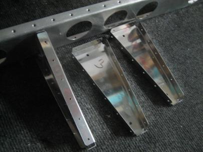
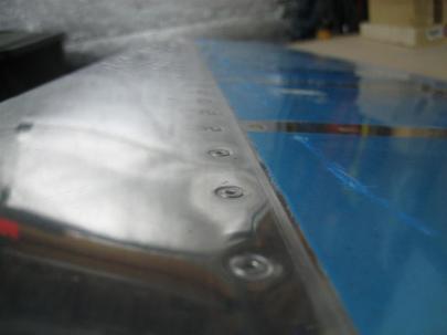
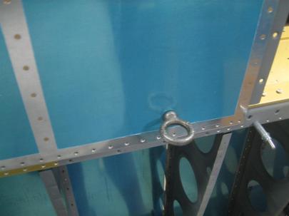
One of the things I have on my list of things to do is to countersink and set the lower inboard rivets on each of the aileron hinge brackets.
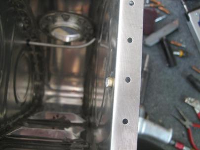
At first I was kind of skeptical that you needed a flush rivet head here, given all the room in the picture…

There isn't anything even remotely close.
…but, after swinging the aileron through its full motion, I noticed that full up (trailing edge up) aileron has minimal clearance there.

Those Van's guys are smart.
Back to the hardware. One of my stocking stuffers from the girlfriend FIANCÉE was this wonderful double-drive ratcheting screwdriver that you’ve all seen on the commercials recently. I have the snap-on one, which is REALLY nice, but this one is great for fast (double drive!) fastener insertions. I’ll use the snap-on when precision counts, and the Kobalt where speed is my friend.

DOUBLE DRIVE!!!
Anyway, I used that with a socket on the end to quickly secure some of the aileron attach hardware.
I’m not sure what order these pictures are in. Here’s me cutting some of the aforementioned AT6 tubing for a spacer.

Action shot!

I don't think I got the edge of the spacer just right when deburring. I might redo this. (This was also the only place I had to make a washer substitution. I used a skinny washer to the right of the aileron attach bracket.

Here's the after shot of the outboard end.

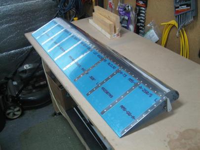
Hey, look at that! It looks like an airplane!
Okay, here, the ADD set in, and I needed to so something else. Time to pull out the flap seal. After edge finishing and scuffing…

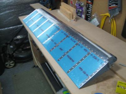
Tada! Time for cleaning and priming.

Don't let the sun fool you. It was freezing out today.
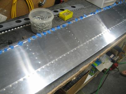
Serisouly, there pictures are way out of order. Here are my rivet counts after I was done with riveting the flap seal on.

29 total rivets set, 1 drilled out.
I didn’t get a good picture, but I didn’t get the rivet gun lined up right, so the edge of the set just chewed through the rivet head.

Anyway, a nice clean drill-out.
Here’s the finished product.

29 rivets closer to the end.
Next, I was trying to figure out how to line up the aileron, so instead of copying some other people’s cleco and a straight edge trick, I decided to do it by the book. Grab a straight piece of wood, drill the holes for the tooling holes in the wings, then line up the aileron with two tangential lines.

Easy enough, right?
Well, kind of. Turns out, I had used one of the tooling holes as the attachment hole for the angled bracket for the wing stands.

See? 1/4"

The upper one is still #21, though.
So, I drilled two holes at the appropriate distance for an AN3 bolt, then drew my tangential lines, then enlarged the lower one to 1/4″.

Worked well for me.
But I quickly realized that with the wing nose-down, the aileron is NOT neutrally balanced. Since there is a moment on the aileron, if I clamp it to my piece of wood, it’s going to bend the piece of wood for a false reading. Looks like I’ll have to actually construct the bellcrank and pushrod.

So, I fished out the bearing from beneath my workbenches and cleaned off the tag.
Also, I found the bellcrank attach brackets.

And cleaned off more tags.
I was trying to locate the AN3-6A bolts that are called out for the bellcrank attach brackets, and I couldn’t find them anywhere.
After about 30 minutes of build time wasted, I remembered that I had one more bag left. I thought this was just the close tolerance bolts, but alas, there were plenty of other AN bolts in there.

This bag hid from me for 30 minutes.
So then I spent about 20 minutes sorting though these bolts.

There are some AN3-6A bolts on the left there.
I have some residual confusion about bolt length, though. Here’s a known -4A and -7A.

Makes sense.

Here's the -6A. This is all good.
Oh, I guess we’re jumping around in pictures again. I’ll bring up my confusion later.
I got the brass bushing out of my storage box and deburred the edges a little.

Shiny is scotchbrited, dull is out of the box.
After inserting into the bellcrank….

Looking good, needs to be drilled to final size, though.
It just barely sticks out both ends of the bellcrank as designed.

Perfect length out of the box.
I did need to drill them out to a #21, though, for the long bolt that goes through them.

This was more difficult than I imagined it to be. I did use wood to clamp these in the vise, and lots of cutting oil for the drill bit.
So here’s where my confusion came back in. I was supposed to use an AN3-32A bolt, but when I held up the longest bolt I could find, (and after verifying that the longest bolt was the appropriate size for the assembly), I held it up to the bolt gauge thing, and it told me it was an AN3-28A. Hmm. I’ve got my three threads on the outside of the nut, so I guess I’m okay, but I’m still confused.
Anyway, now that I’ve got the bellcrank available, I need the pushrod.

Here's a closeup of the pushrod I'm going to make.

Here's the rest of the W-818 assembly.
After carefully measuring and cutting, here are my two pushrods.

One left, and one right.
After drilling two 90° #30 holes…

You can also see an AN470AD4-12 rivet.
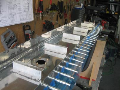
Then, after some rivet squeezing and priming, I propped it up on my handy-dandy cleco storage units for drying.

It's like watching paint dry.

A picture of the rivet shop heads.
Oh, and one more spacer for the actual attach point for the aileron.

More spacers!
Here’s the attachment for the aileron.

This angle is weird because I've flipped the entire aileron up and around its axis.
But, after I got the pushrod installed…

Looks like an airplane!
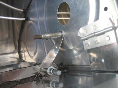
Here’s the bellcrank area. Looks like I dripped some primer in there.

Van's tells you to prime the inside of the pushrods, too. So I poured some in there, then tried to pour it out. None came out until I installed it here, and some seeped around the edge of the pushrod fitting. Oops.
Hey, not to far off for the first try.

Within a degree or so...I'll fix this first thing tomorrow.
4 hours total today, 3 of which were on the ailerons, 1 of which was for the flap brace. 29 rivets set, one drilled out. Yahoo!
Prev | Next


 Posted by Andrew