Started Leading Edge Landing Lights

January 16, 2011

Prev | Next

Well, after receiving my “install only” leading edge landing light kits from Duckworks, I was kind of eager to start fiddling with something other than rib preparation.

Today, I opened up the kits and started in on adding the leading edge landing lights.

This is from my design page, where I’ve been collecting ideas for stuff (I was originally planning 2 small MR16 (2″ sized) lights in each wingtip, one taxi, and one landing):

After reading a little more, I’ve found that people who do the two lights in each wingtip dance aren’t happy with the amount of light they are getting from their landing/taxi lights. Then, I figure out they are talking about the regular halogen bulbs provided with Van’s wingtip light kit.
The people who are using the HID wingtip lights are generally very happy with the light output.

November 2010 update: After even more reading, I’ve decide that the leading edge light is really the way to go.

Now, I think I am going to put a single HID (PAR 36 style) in each leading edge for landing lights. These won’t wig-wag.

Then, I’ll use the wingtip lights for taxi/recognition, with wig-wag. I can use the smaller MR16s in the wing, and point one set wide, and one set toward the centerline. If I use regular halogen bulbs in these, I won’t have to use a warm up circuit, which is good, considering that when up at cruise and ATC calls with a traffic alert, I’ll be able to immediately start wig-wagging them for recognition. That gets rid of my need for an automatic warm up circuit (won’t be using HIDs for wig-wagging).

I’ll figure out the mechanics of the wingtips taxi lights later (single light in each wing? 2 MR16 halogens in each wing?)

Anyway, I made the decision to go with the dual landing lights in the leading edges. I plan on flying at night, and I want the most light possible.

From Duckworks, I ordered two of the round install kits, and two H3 enclosures (spot, instead of flood). I could have ordered one spot (for landing) and one flood (for taxi), but since I’m going to do something in the tips for taxi, I want both of my leading edge lights for landing.

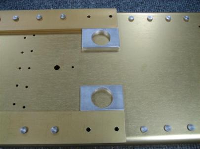
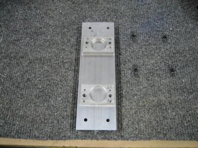
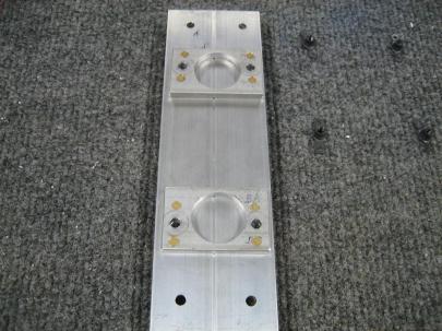
Anyway, here are the two kits. Very obvious are the two mounting plates, the bulb retainer, the lens retainers, a bag of hardware, and the leading edge lenses.

Duckworks was kind enough to send me a spare lens. Much appreciated.

Here are the two PAR 36 style, spot enclosures for an H3 bulb. My soon-to-arrive HID kit should have H3 bulbs that will fit nicely in here. I’ll do a separate write-up for those.

I left the bag on them to prevent getting any skin oils on them.

A closeup of the H3 part of the enclosure. I had never seen one before, so this was a learning experience for me.

Also included in the kit are the instructions, an exploded view, and the templates for the cutting and drilling.

Good documentation. Well done.

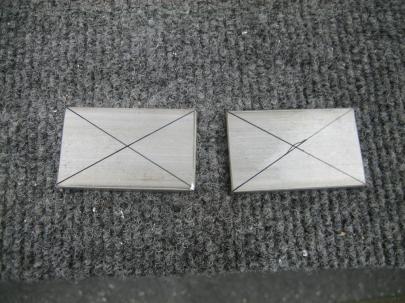
Anyway, I decided to just bite the bullet and cut into the leading edges. Here is the template with the middle cut out.

Template, ready to go.

First, I cut out the rib template and used a sharpie to mark the hole locations.

Exact positioning here isn't too important because the holes in the mounting plate are huge, and you can adjust these a fair amount.

Back to the cutout, I measured the 2.5″ from the edge of the cutout to the row of rivet lines.

Special note here, I cut the paper off on the left edge of the following picture so I could leave the ribs clecoed in. This just meant I had to measure from the cutout instead of using arrows on the side.

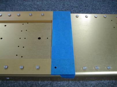
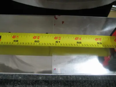
I also measured per the plans (18.75″ from the aft edge of the top of the leading edge skin to the top part of the opening here) and taped everything in place.

Tracing with a sharpie.

Same trace, no paper.

Other wing.

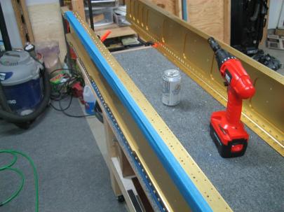
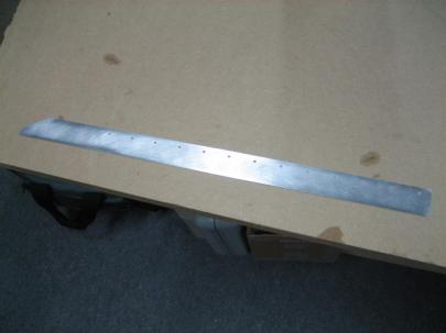
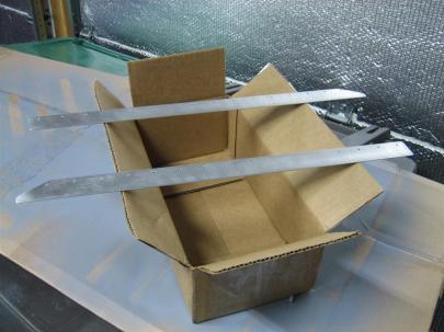
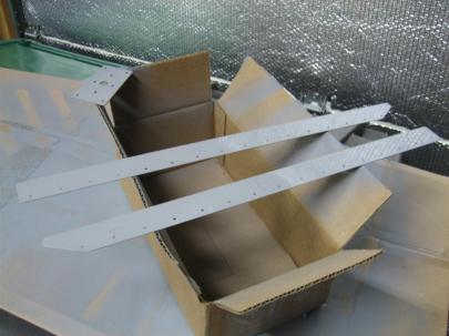
Before jumping into the actual cutting, I moved on to some of the metal preparation for the other stuff. I wanted to be able to cut the leading edge openings while the primer was drying for some of these smaller parts.

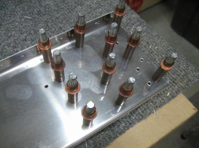
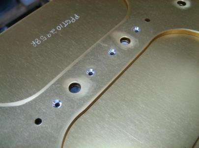
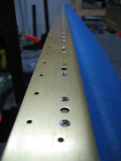
Here, I’ve run a #40 bit through all of the nutplate attach holes and enlarged the middle holes to 5/32″ per the instructions.

Then, I clecoed all 4 pieces together to countersink the nutplate attach holes for regular AN426 rivets. I could have used “oops” rivets here, but the lens retainers are thick enough that it wasn’t necessary.

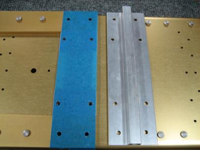
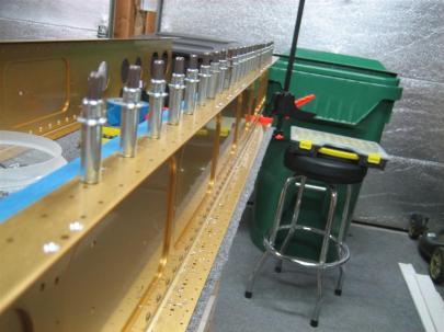
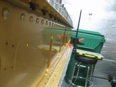
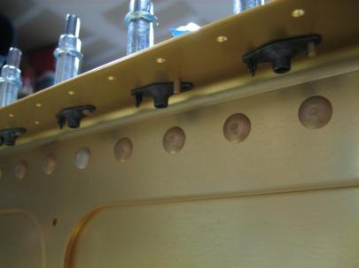
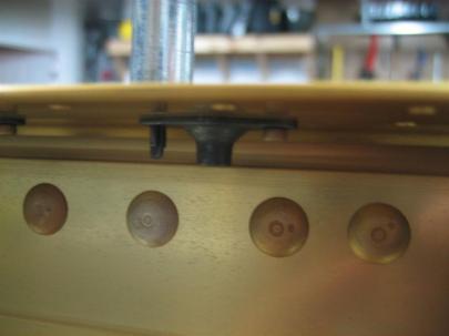
4 lens retainers, clecoed together to give the countersink guide a good path.

I forgot to take any pictures of the rest of the prep for the lens retainers, lamp retainers, and the mounting plates. Anyway, they got prepped, cleaned, dried, and taken outside to prime.

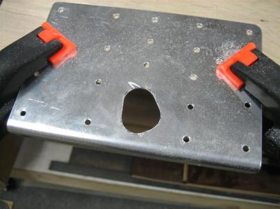
I headed back in and got out a variety of dremel tools to cut out these openings.

There’s no turning back now.

I started near the bottom (least visible) and very far away from my line. As I gained confidence, I moved closer to my line (less finishing later).

Yikes, that's not a pretty cut.

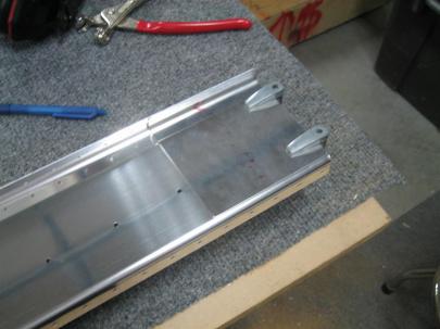
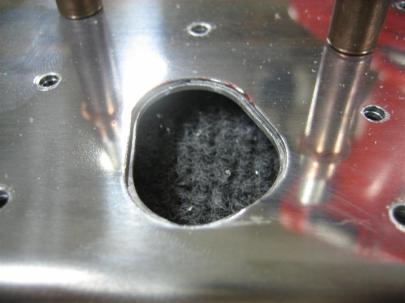
After a little cleanup, they look a little better. Still need to do some final cleaning.

I didn’t take a picture of the other cutout, but it turned out equally as well. A lot of people really stress out about cutting these holes.

I can see where they are coming from, but I think the leading edges are great with these light openings in them. (I’m going to look like a 747 coming down final, which is exactly what I want (visibility and recognition).)

Pretty leading edges. (Oh, and this was the first time in a long time I've been able to work with the garage open. It was almost 40°F today!)

Okay, back to the primed parts. I had the urge to set some rivets today, and I nailed all of them. I finally feel like I’m starting to get into a groove (although squeezing really isn’t that hard.)

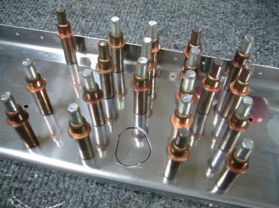
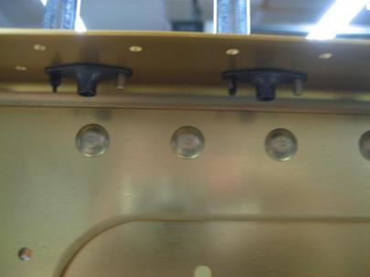
Here, I’ve clecoed the provided nutplates to the lens retainers.

Ready to start some riveting.

A closeup of some AN426AD3-3.5 rivets.

24 rivets set (beautifully).

Equally beautiful shop heads.

8 more rivets set (I did use "oops" rivets here).

More shop heads.

I got out one of the bulbs and just placed it in the mount just for kicks.

Looks like it will fit.

Found the screws and actually screwed them in. These things are going to look awesome.

Finally, I found all the pan-head screws and lightly screwed them in place.

Sweet.

I don’t think I’ll do any further painting of these. I like the primer grey.

I’ll do some more on the landing lights soon, but for now, I need to get back to rib prep. Hopefully this week I’ll have a writeup of the HID kit that arrives.

3.5 hours, 32 rivets. Wuhoo!

Prev | Next


More Right Tiedown Work, Started Right Rear Spar

September 5, 2010

Prev | Next

Whoa, it’s been awhile since I actually got any work done on the airplane. I’m going to blame my exploding lawnmower (long story), business trips, and the wood floors project.

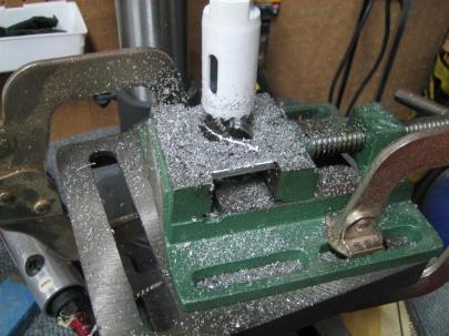
Anyway, I managed to find a good bi-metal hole saw from the aviation department at Lowe’s, so I chucked that thing up in the drill press and started in on the spacer lightening holes.

Under all that mess is a spacer with a freshly cut hole in it.

I am not really a fan of cutting those things this way, but I don’t have a fly cutter (apparently the one from Harbor Freight sucks), so this was the best I could do.

They actually turned out really nicely.

Two spacers, that go against the spar web.

Like many other builders, I taped them down before putting the tiedown bracket in place, flipping the spar over, and matchdrilling the remaining 7 holes.

After everything has been matchdrilled, I pulled it apart. Looking good so far.

Then, I skipped a couple pictures, but basically You bolt the tiedown bracket, spacers, and nutplates in place and use the nutplates to backdrill the attach holes (small ones on either side of the bigger holes). They all turned out great, except for the upper left set, which for some reason are a little crooked. It doesn’t matter what the nutplate ear orientation is, I was just annoyed they didn’t turn out perfectly aligned.

Somehow that upper left one's alignment got away from me.

Then, you have to countersink the nutplate attach holes (this side of the spacers must sit flush against the spar web).

These rivets aren't set (I still have to prime all these pieces), but I just put them in there to see how my countersinks were. (The lower left one is a little deep, but this is thick spacer, so it shouldn't be a big deal.)

I don’t have any primer, so I decided to move forward (“aft”?…ha…airplane coordinate system joke) to the rear spar. After getting out the W-707A rear spar channel (make sure to grab the correct one, there’s a left and a right) and the W-707E and W-707F doubler plates, I took the blue plastic off of everything and started getting things clamped in place.

The W-707F is laterally aligned with the outboard edge of the rear spar channel.

The W-707E gets laterally aligned by measuring; the outboard edge of the doubler plate should be 50 3/4" from the outboard edge of the rear spar channel. Easy enough.

Then, I fired up the air drill for some matchdrilling.

{air drill noises} Whose finger prints are those?

{more air drill noises} Also, I traced out the aileron pushrod hole onto the doubler plate.

After some though about how to do this, I decided to forego the step drill (Unibit) trick (I don’t have a Unibit…how’s that for a trick!) and just drill some holes and then get the dremel out.

It turns out that all the little fancy metal saw and milling tools aren’t really as easy to use as the 1/2″ sanding drum . Save yourself some time and just get the sanding drum out. Very easy to control.

Looks pretty good to me. (This crazy little torture device that looks like a saw got away from me and cause that scratch. I'll have to buff that out.)

After clecoing back to the spar turns out the thickness of my line made my initial pass a little small. (Better small than big.)

More sanding, anyone?

Much better (still needs some edge finishing).

I totally forgot. Even though I don’t have primer to finish up the tiedown bracket, I can still tap the tiedown hole.

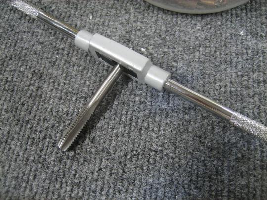
Here's the 3/16" x 16 tap.

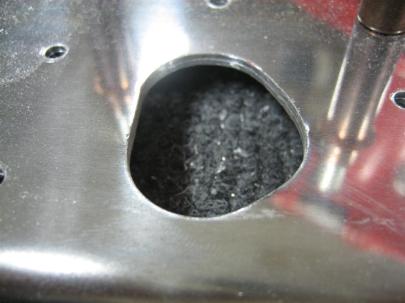
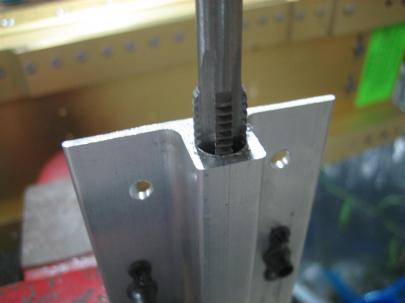
After having a hell of a time getting started, they turned out really nicely.

1 full turn in, 1/2 turn out. Wash. Rinse. Repeat.

I managed to get both brackets done, even though I really haven’t started on the left wing yet.

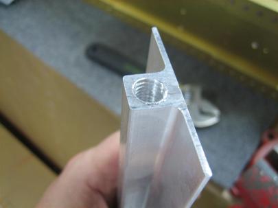
I'll need to deburr the edge, but this should work just fine.

I ended up going to 1 1/4″, even though the directions tell you to only go 1″. Some other builders had to go deeper once they actually got their eye bolts, I figured it would be easier to do now than to wait until the brackets are in the wings.

2 productive hours today.

Prev | Next


Started on Right Wing Tie-down Bracket

August 26, 2010

Prev | Next

Wuhoo, the new squeezer showed up!

After a few minutes of messing around with it, I grabbed the two K1000-4 nutplates and studied the plans carefully on which side of the spar they go. A quick hint (other than just reading the plans) is that the nutplates go on the side that couldn’t possibly need to be flush (in between the spar cap bars).

Anyway, here, I’ve countersunk for AN426AD3-6 rivets.

The two larger holes are examples of where Van's (or Phlogiston) buffed out some spar scratches with some scotchbrite.

Oh yeah, I also flipped the spar over and deburred (you can hardly see the deburring) the backside of the holes I drilled to #40.

The little silver rings are where I deburred. Because these will be totally covered by the nutplate and the shop head, I'm going to refrain from spot priming them.

I used the new squeezer to set my only 4 rivets today.

Don't these look pretty? (There are small rings around the rivet heads. That is from the cleco I used to hold the nutplate on while riveting the other side.) It seems weird the cleco made that little mark.

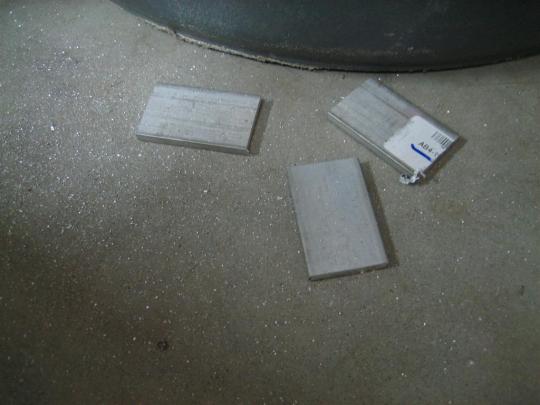
Moving on to the tie-down bracket. First thing, I need to fabricate the W-726 spacers from this 1.25″ wide angle stock. I’m supposed to cut 4 of them, 2 for each wing/tie-down).

Why is this one on the ground? Is it because the light is good for the camera? NO. It's because it is @&*!@ hot after cutting. Ask me how I know.

Here are the other three.

Each of these spacers should have a 1″ hole cut in the center for lightening (not lightning). Since all of my hole saws are in sizes other than 1″, I decided to grab the W-731 tie-down bracket and get to work on that.

Okay, the manual says to cut the tie-down bar to length from the AEX stock.

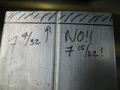
Okay (…searching plans…), looks like 7  15/32″. Of course, I measured 7  7/32″ marked, and almost cut before my gut told me something was wrong.

The bar is actually 7 16/32" ( or 7.5"), so I'm not going to cut them 1/32" when I'm sure the edge finishing on the scotchbrite wheel will be more than enough. (Also, it doesn't appear the extra 1/32" will interfere with the top or bottom skin at all.

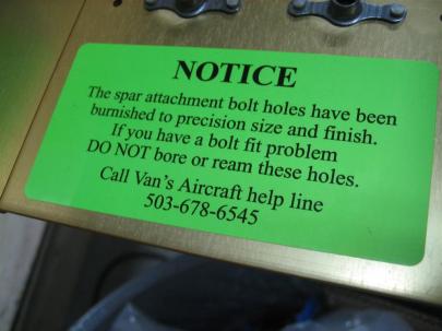
I keep walking by this sticker and laughing. I thought I would share.

Translation: "If something doesn't fit right, you've royally screwed something up."

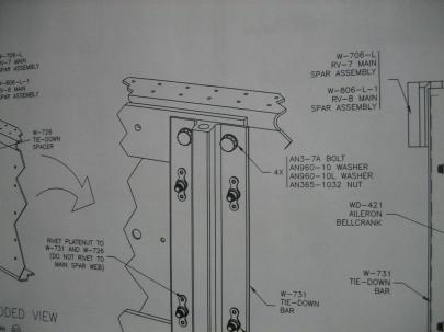
Okay, back to the tie-down. After marking and drilling the one (of four) holes for the spar in the bracket to 3/16″, I stuck an AN3-7A bolt in there and just eyeballed the alignment.

(You are supposed to drill just one, then fit the bolt through the whole assembly. Then, you flip the entire assembly over and matchdrill the tie-down bracket from the back.)

I was a little concerned that there was some overhang on the right side of the bracket. (I measured and drilled very, very carefully).

Looks like there is some overhang on the plans, too. Sweet.

Anyway, I stopped there because I can’t really matchdrill everything until I get the spacers placed behind the tie-down bracket, and I can’t really do that until I have the lightening holes drilled (the spacers will be riveted to the tie-down brackets in four places, which in turn hold some nutplates on).

Here are my spacers for the right tie-down bracket.

1 hour, 4 rivets.

Now, I need to find a good hole saw or fly cutter.

Prev | Next


Right Spar Countersinking and Nutplates

August 22, 2010

Prev | Next

Well, today was the first official wing construction day. While Van’s is trying to figure out what to do with my damaged left spar, I figured I should get started on the right spar.

First thing…yup…a plans change picture!

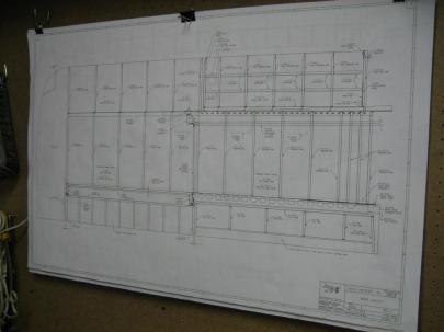
The plans for the wing are a little different. There are about 4 separate sheets of different views for the wing. You guys get to see just the general layout one.

Wuhoo! A wing!

Now, let’s get to work. First thing, I very carefully put my beautiful right spar on the edge of the workbench and clamped the flange down very lightly. The spar will tip over onto the table (away from the camera) if the clamps let go, so I’m not too worried about clamping them down too much.

Every builder that has a website makes a comment here about how the construction manual really holds your hand and steps you through the process on the empennage, but then kind of just makes general statements for the wing. For example, the only real construction step on the first page of the wing section says:

“To begin wing construction, rivet the tank skin attach platenuts to the spar as show in DWG 16A, Detail A. Machine countersink the platenut attach holes in the W-706A spar flange.”

Wait. What? That is like 1000 steps, condensed into one statement. It ended up taking me 3.5 hours to do that one step (I admit, I also delved a little into a step a few steps down):

“Attach the K1000-06 platenuts for the W-822 access plate to the W-706A flange. See DWG 12.”

Fine. I see how it’s going to be.

Let’s get started.

Where is my countersink?

A lot of builders start out thinking they should make a nutplate jig and countersink the screw holes before riveting the nutplates (sorry Van, I call them nutplates) on so they can use the jig as a guide for the c/s pilot to avoid chatter. Van’s suggests using the installed nutplates as the pilot guide. After those builders spend some time making those jigs, they eventually abandon the idea and fall back to the Van’s method. I’m going to do something I don’t normally do and FOLLOW THE INSTRUCTIONS. Sometimes, I try to get cute with extra ideas and fancy engineering solutions, when really I should just do things by the book.
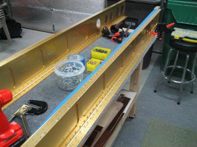
So I grabbed my countersink with a #40 c/s bit, tested in some scrap, and positioned the countersink cage over one of the nutplate  attach holes.

The c/s pilot didn’t fit. What?!

You mean I am going to have to drill all of these holes out to #40 first? Ugh!

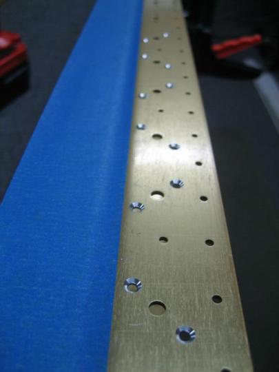
After drilling every one of the attach holes out to #40, I finally got the countersink and cage loaded back into my cordless drill (slower and more trigger feathering ability than the air-drill) and got to it. Here are my first 10 countersinks.

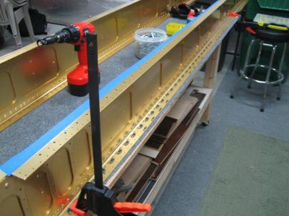
The blue tape is to prevent metal shavings from getting lodged in between the spar cap bars and the spar web.

Anyway, I continued down the row, being very careful to slow myself down and not to fall into too much of a routine. I could feel this was going to be one of those areas where I would be going through the motions and mess something up. (I did make a mistake while drilling out all the holes to #40. I accidentally drilled out a skin attach hole, too. No biggie, but a perfect example of moving too quickly in a habitual way.)

I stopped about every 6 countersinks and retested my countersink depth using a AN426AD3-4 rivet. They are all perfect. Here is the end of the row, looking back toward the “diagonal” wing-walk attach holes.

Pretty, pretty.

Then, I flipped the spar over and did the bottom flange. Also, there are some access panel nutplate that get attached now, too. I went ahead and countersunk for those attach rivets, also.)

Bottom flange, sobriety-maintaining Sprite-zero, and the girlfriend's cordless drill I'm borrowing (pronounced "you can have it back when you pry it from my cold, dead hands"). Thanks girlfriend!

Phew, that was a lot of countersinking. (I think I counted 144 total countersinks for just the nutplate attach holes. There’s another 72 for the screw holes (in the middle of each set of three holes) I’ll have to do later.)
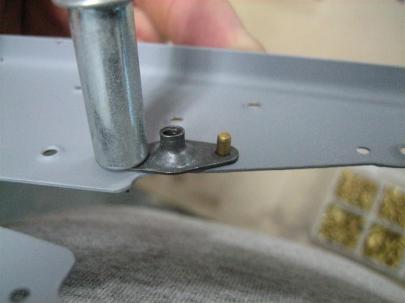
Next, I grabbed some K1100-08 nutplates, some silver 3/32″ clecos, and some AN426AD3-4 rivets and started getting ready. My plan is to cleco the nutplate to the spar, insert one rivet, then after riveting that one, take the cleco out and rivet the other side.

Cleco in one side, unset rivet in the other.

Down the line, everything ready to rivet.

Redundant picture.

Ahh, this slower, more thoughtful approach is paying off. Can you see the error that I almost made?

Which one of these is not like the other?

Here's an example nutplate before I take the cleco out and put the other rivet in.

I can’t remember why I took this picture. I think I just took out all the clecos, and I thought it looked cool.

Ready to set the second half of the rivets.

No pictures of the second rivets, but here’s one of the other (now top) flange.

You can see all of the nutplates on the lower flange.

Anyway, I set all the nutplate attach rivets on the upper flange, and then called it a day. So I got to cross off the two statements in the construction manual I highlighted above, and next up is to use the installed nutplates as c/s pilot guides for countersinking the screw holes.
Oh, and then I get to repeat on the other spar.

3.5 hours of countersinking and riveting today. 144 rivets, 1 drilled out (the rivet split in two!). Good times.

Prev | Next


Started Riveting Left Elevator Skeleton

July 5, 2010

Prev | Next

After the last couple work sessions priming various parts, I was getting all hot and bothered to rivet something. I thought I would tackle the spar reinforcements. I also forgot to charge the camera battery, so I’m using the new phone. Hopefully they turn out okay.
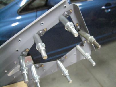
Here's the left elevator spar and reinforcement plates.

I got out a few rivets. AN470AD4-5 and -6.
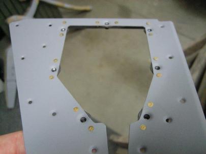
Let's get riveting.

I clecoed the reinforcement plates and nutplates onto the spar, and riveted the four corners and one ear of the nutplate, then took out the clecos and riveted the rest.

The tape is a trick I have been using out of vanity. The rivets look better when they haven't been marred up by the rivet set.

After doing both plates, I put the spar back on the table.

Pretty.

And just to show you AGAIN how much I love my new tungsten bucking bar, here are the perfect shop heads.

The inboard shop heads.

The outboard shop heads.

Next up is to continue riveting on the skeleton, so I pulled E-705 out of the “recently match-drilled” pile and got it deburred, dimpled, edge-finished, and prepped for priming.

Ready to prime.

This is the other side after being shot with primer.

16 rivets set in 30 minutes of building after 30 minutes of shop cleanup (cleaned out the shopvac, etc).

Prev | Next


Riveted Right Elevator Skeleton

May 13, 2010

Prev | Next

Well, I’d been waiting for a couple days for an order from Aircraft Spruce to come in. I ordered a whole bunch (~60) #6 screws and nutplates to use to attach the emp tips, and added a couple 1/4″ nutplates to attach to the elevator counterbalance spars so I can add more weight later for fine elevator balancing.

Here’s the deal. When you initially balance the control surfaces (without paint), you can either leave them a little heavy (which some do), or balance them exactly. Given that I might leave my empennage polished, I thought I would go ahead and balance them perfectly for first flight, then rebalance (pronounced “add weight”) after paint. While the forward tooling hole in the counterbalance ribs would work for a straight up bolt and nut, I’d prefer a nutplate. Also, since the two counterbalance ribs are butted against eachother, I’d prefer to drill for the nutplate now, so I can deburr both sides of both surfaces.

(I wonder how people deburr holes drilled through two permanently attached skins. Maybe just the inside and outside of the two skins and not the middle two surfaces?)

Anyway, here’s the order.

screws and nutplates.

Both size #6 screws in their new home.

I'll definitely be able to tell the difference between the two sizes.

Here are the 1/4″ nutplates. I bought one-lug because I thought the second lug might interfere with the An509 screw and nut used to attach the elevator counterweight. I’ll point it out again later.

MK2000-4 nuplates.

Then, some of the smaller MK2000-06 nutplates. I bought these for some of the tight locations on the emp tips.

I forgot to take a picture of the 60-odd 2 leg nutplates.

Okay, now on to real work. Here I am trying to figure out how to get this thing in a place where I can drill it. I don’t have any 1/4″ clecos, so I had to just eyeball it. That was a bad idea.

After one of the #40 holes drilled.

Here's the second hole drilled. You can see I had to enlarge the tooling hole to much bigger than 1/4" because I am lame and didn't have a 1/4" cleco to located the two attach holes. Lame me.

After taking those apart and deburring the holes, I scuffed everything up, leaving only the four rear-most holes on the E-703 End Rib. Again, I use the rivet in the hole into the countersunk steel bar trick.

Ready to flush rivet to form this dimple.

I have a 5/8" flush set, which comes in handy in some places.

Both done.

After cleaning those two ribs, I set them aside to dry before priming. Then, I moved on to the WD-605-R-1 Elevator Horn.

Let's see. AN470AD4-4 rivets. I might have some of those.

A small smiley on the lower left rivet, but according to the diagrams, it is okay.

6 nice rivets. The shop heads are very nice.

See? Told you.

Then I shot the six on the other side of the horn.

I love this new tungsten bucking bar.

6 more down.

Back to the paint booth.

E-703 End Rib and E-704 Counterbalance Rib being primed.

And now, a big pictures shot of the elevator horn on the skeleton.

It's starting to look like an airplane.

Then, I deviated from the plans (like many builders here.) It is easier to attach the E-704 Counterbalance rib to the spar if you don’t rivet it to the E-703 End rib first. I managed to massacre the left head, and the flange on E-704 didn’t sit flat against the skin on the other side.

Whoa. Take it easy, Andrew.

I don't like how the flange isn't flush with the spar web here.

Time to get the drill out.

Drilled first with #40, then #30 through the head only.

Pop the heads off.

Then re-set. This is a little better.

But not perfect. I think it's going to be good enough. I'd rather see them sitting perfectly flat, but the area around the rivet is sitting where it should be. It's just around the edges of the flange that are standing off a little.

Here are the new manufactured heads. Much better.

There we go. What's next?

Okay, now I need to attach the E-704 to E-703. Wait a minute! There is no rivet callout for these.

I see one for E-703 to E-702 and for E-704 to E-702. Where is the E-704 to E-703 callout? Well, I guess I'll just use AN470AD4-4 rivets.

Yikes.

The three upper middle rivets are all horrible. I can't figure out why the gun is jumping around so much.

Anyway, before drilling those out, I wanted to get that nutplate riveted on. Same deal here, though. I couldn’t figure out how to cleco it on for riveting.

Here are the two NAS1097 rivets ready to go.

I ended up shooting both of these at once. (How cool is that?)

NAS1097-4 (I think they are -4s)

I held the bucking bar on the other side and used my finger to hold the nutplate firmly against the web of the rib.

Is this a good method? No. Did it work? Yes.

Anyway, in the above picture, you can see one of the three rivets that I botched. After drilling all three out, I reset 2 successfully, but messed up this one again.

Grrr. It didn't really bend over, but it kind of shifted to one side.

Drilled it out, then did the exact same thing. This is the third time I’ve drilled out a rivet on this hole.

Grrr.

I figured out that during the first try, I had bent the rib web a little, so the rivet was pre-inclined to lean. I took my tungsten bucking bar and my 5/8″ flush set (without a rivet) and got everything flattened out again. Next try, the rivet set well.

Top middle rivet. Much better.

Finally, an upside down picture of the right elevator skeleton.

Tomorrow, I'll get back to work on the skin. Maybe this weekend I'll have an elevator!

2 hours, 26 rivets. 5 drilled out (3 of those was one hole!)

Prev | Next


Riveted E-615PP Trim Reinforcement Plate

April 6, 2010

Prev | Next

WUHOO, tool order arrived!

3 things in the order, $154.90. Ouch.

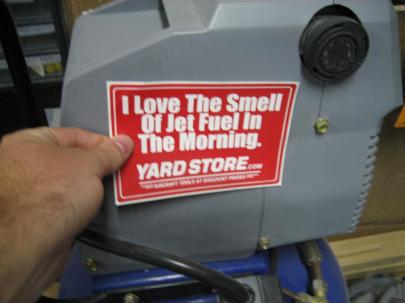
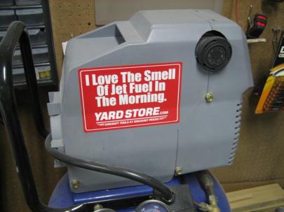
Also included was this AWESOME sticker.

Where should I put this?

Here?

Here?

Here?

On the airplane? no.

Finally, the air compressor won.

Decorated air compressor.

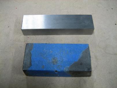
Look at that beautiful tungsten bucking bar.

Old and new.

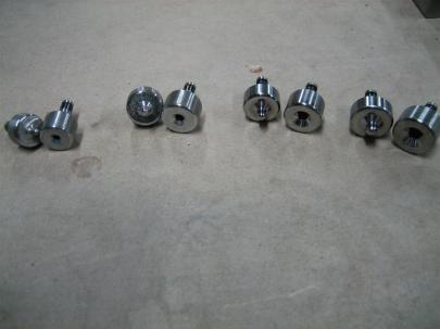
Also, I got two more dimple die sets. #6 and #8, on the right.

Just for comparison. #40, #30, #6, #8. Still need a #10.

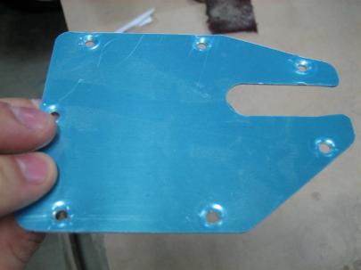
Alright, back to work. First up, using the #6 dimple dies on the E-616PP Trim Cover Plate.

Nicely dimpled. I don't think it matters that you take off the blue vinyl. Maybe that was a bad idea.

Here’s the bottom side (top side when mounted on the bottom of the elevator on the airplane).

Peeling off the blue vinyl.

Then, edge finished and scuffed for priming. I’m going to wait to prime this until I can actually by the electric trim motor since you have to drill more holes. Just thinking ahead: can I countersink and use NAS rivets for the trim motor mounting brackets? Nope. These are pretty structural (hold the motor, and therefore the trim tab, in place.) I’m sure those directions will confirm the need to dimple. I’ll need to dimple E-616PP and the brackets that are used to attach the trim motor.

Ready for priming, except for all of the extra holes I have to drill, deburr, dimple, and rivet.

Same deal on E-615PP.

Ready for priming.

On the fancy priming stand.

After shooting primer to one side of E-615PP, I decided to add 4 holes for each of my new dimple die halves.

4 holes drilled.

Tada.

7/32″ seems to work well for holes in a home-made dimple die holder stand.

7/32" is a good size hole for these.

Then, I shot primer on the other side of E-615PP. While I waited for that side to dry, I edge finished E-616PP.

Look at that nice edge. I love the scotchbrite wheel.

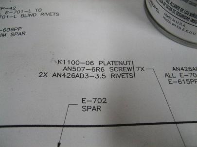
Now that E-615PP is dry, let’s do some riveting! I grabbed the K1100-06 nutplates (or platenuts as Van calls them) and the 14 required rivets. Remember from March 28th, I am using NAS1097 rivets here.

I am going to be using NAS1097 rivets here (smaller head than AN426 rivets) so I can countersink (instead of dimple) the holes here. That saves me from having to dimple the nutplate ears, which will save me a lot of hassle.

I finally found the rivet callouts.

I thought that because I countersank (verb tense?) the reinforcement plate that the 3.5 would be way too long, but the -3 was definitely too short. I grabbed 14 NAS1097AD3-3.5 rivets.

-3.5 (length) should work here.

I put all of the nutplates in with a single cleco and a single rivet, taped into place before starting to squeeze them. I hindsight, I should have backriveted these. So dumb.

Half of them done.

Then I did the other half.

Nice and flush. There is one that is almost proud, but doesn't affect the cover plate, so I may not try to muck it up further by drilling it out. We'll see if I can sleep tonight.

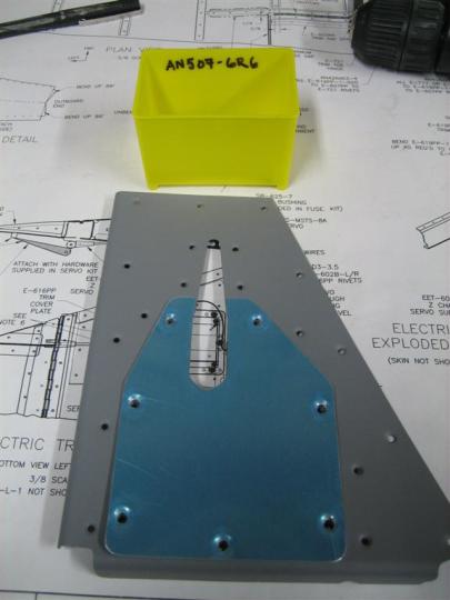
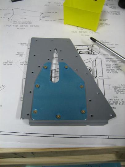
Once I got those 14 set, I grabbed the An507-6R6 screws and got the cover plate screwed on.

Ready to screw down. see in the lower left where the shadow under E-616PP is a little bigger? The dimpling kind of warped the plate. I'll have to try to coax this flat again.

I couldn't get the screws in all the way without a lot of effort. Is this normal for nutplates?

Anyway, 14 rivets set in just under an hour. I’m going to mark an hour today (a little long), then short myself on a post in the near future.

Prev | Next


Primed R-918s and R-608PP

March 14, 2010

Prev | Next

After a whole 10 days on vacation, a few flight delays, cancelled flights, rebooking to a city 6 hours away from home, lost bags, malfunctioning 737s, and a broken down rental car, I finally made it into the shop.

I know I wasn’t going to be able to put in hours and hours of work, but in the words of Bob, “baby steps.”

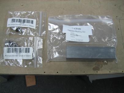
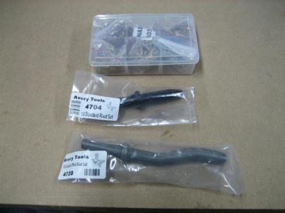
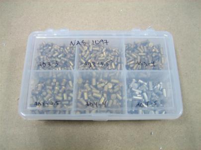
First of all, while I was gone, I got an order in from Avery. It contained the NAS 1097 “Oops” rivet kit, and two sets, both 1/8″, one straight, and one double offset. These were relatively cheap ($8 and $20, respectively) and I believe they will come in very handy. Here’s the merchandise.

I love buying tools. It's like crack, but more legal.

After unpacking the new tools, I finished deburring and edge finishing the R-918s.

A deburred and edge-finished R-918. I'm not sure which side this due to the glare in the picture. But you don't really care, though, do you? They are identical parts (although, make sure to keep them separate, because they've been matchdrilled to the rudder skins).

I shot a little primer on one side of those two pieces and started deburring and edge finishing R-608PP, which is the uppermost spar reinforcement plate. I shot a coat on one side of that, and the other side of the R-918s.

Ready to prime R-918s.

R-918s and R-608PP primed. They are still wet, which is why you can see the reflection of the garage insulation on the R-918s.

While waiting for those coats to dry, I unpacked my Oops rivet kit.

Which one of these labels isn't like the other?

All done and labeled.

I didn't have any more room in my rivet "briefcase" so I'll leave them in the included case.

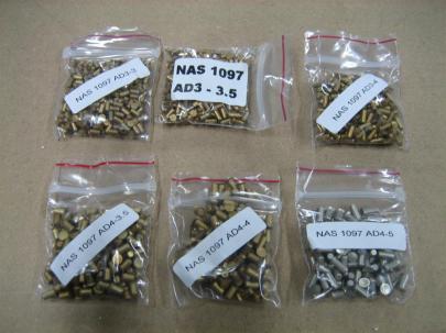
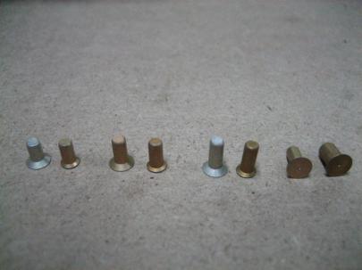
Then, in a similar manner to Brad Oliver’s explanation page (another shot here), here’s my shot of some NAS 1097 rivets next to their AN426 counterparts.

AD3-3, 3.5, and 4 (AN426 and NAS 1097 of each to compare smaller heads for the same size rivet) and on the far right, an AN426AD3-3.5 and a NAS1097 AD4-3.5. Same size head.

From my understanding the AD3 (smaller) sizes are used when a smaller rivet head allows you to countersink thinner material (instead of having to dimple) in non-structural areas (dimples aid in the strength of the riveted pieces). Mostly, they are used where flush rivets are required to attach nutplates (so you don’t have to dimple the nutplates, which is apparently difficult).

The larger size (AD4) rivets are used primarily when you have messed up an exterior hole during riveting or drilling out a badly set rivet that you have to enlarge the hole. The smaller heads on the larger rivets match the regular sized rivet heads.

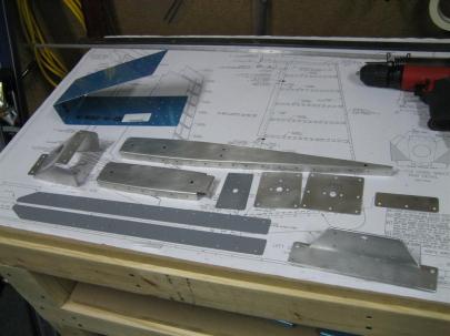
Once I got primer on those three parts, I put them back on the “table o’ small rudder parts”, to give you a good understanding of how much more tedious prep work I have to do before I can start riveting parts together. I can’t really complain. I love this stuff.

3 of 11 parts primed (and these are just the small parts).

A short half an hour today. Felt good.

NEXT DAY UPDATE:

CRAP!

Because the R-918 (rudder bottom fairing attach strips) go under the rudder skin and bottom rib, they need to be dimpled, and I forgot to do that last night.

Let’s see, rudder skin = regular #40 dimple dies, bottom rib = #40 tank dies, which means I’ll have to use the #40 tank dies on the R-918s, too. I wonder what the dies will do to a part that is already primed. I’ll give it a shot, take some pictures of the results, and re-prime if necessary. Boo.

Prev | Next