Primed R-902 Rudder Spar

March 18, 2010

Prev | Next

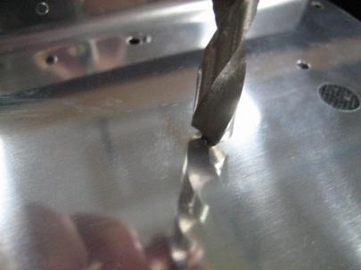
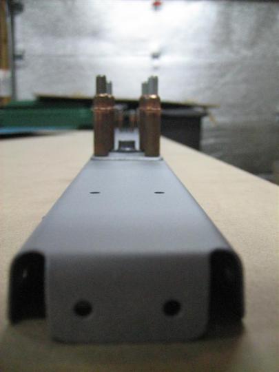
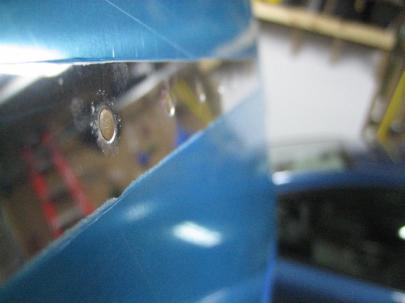
I was getting the itch to work on the airplane a little, so I tackled the R-902 Rudder Spar today. First thing, deburring. I know I have plenty of pictures of deburring , but I took a closeup of a few holes.

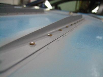
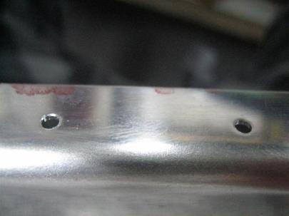
Hole on the left is deburred, hole on the right is not. This is the topside, though, so the raw hole on the right doesn't even have really bad burrs. The weird crap on the left is just a piece of metal left over from deburring, it's not really messed up.

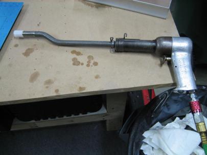
Here’s an action shot of me using the oversized bit to deburr.

Action shot!

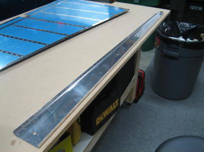
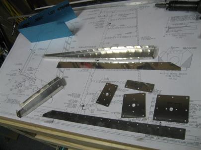
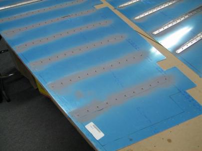
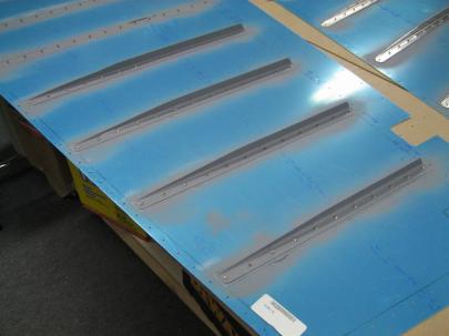
Here’s the spar, deburred, and ready for scuffing, cleaning, and priming. Sorry for all the pictures tonight.

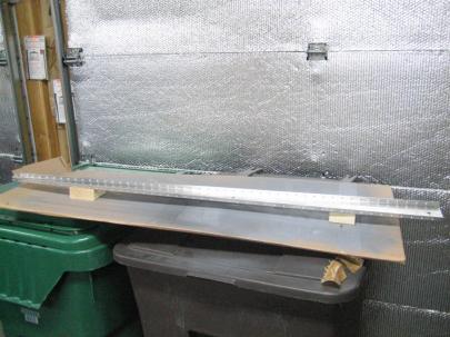
R-902 Rudder Spar

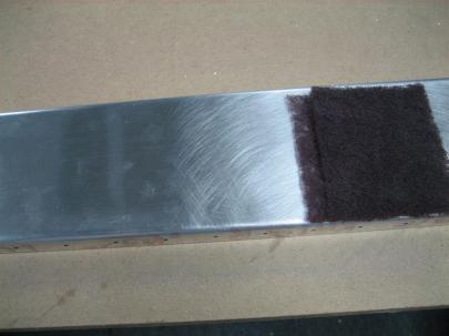
Here’s a picture of me scuffing with my maroon scotchbrite pad. For some reason, I like this step in the airplane building process.

Left half is the raw spar, right half has been scuffed.

Then, Ginger noticed I was in the garage working, and since the garage temperature was the same as the house tonight, I left the door open.

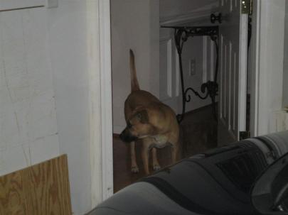
"Jack, come out here and let's see what dad is doing."

Jack came to see what was going on.

Jack and ginger, curious as always. (They are collarless due to the baths they just got.)

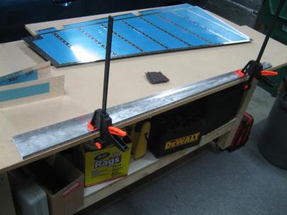
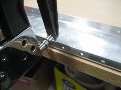
To scuff the inside, I decided to clamp the spar down to the table. It makes scuffing slightly easier, and I can use two hands on the edges.

Some of my nice (but cheap) clamps from Harbor Freight earning their keep.

Next up, dimpling. The construction manual warns to maybe grind down the dies to make sure not to gouge the spar web. I didn’t seem to have any issues with clearance.

Dimpling with #40 tank dies.

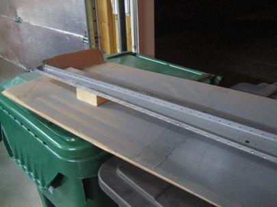
Then, I took the spar inside and cleaned it with dawn dishwashing detergent. Then back outside to dry for priming. Here’s the spar in my fancy paint booth setup.

Spar, ready to be shot with primer.

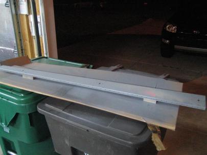
I did the forward side of the spar first. (Notice the open garage door, I’m trying not to kill too many brain cells with the priming.)

Forward side of the spar primed.

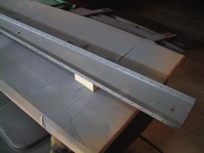
A shot of the lower portion of the spar.

Then, after going inside to refill the wine glass (to let primer dry), play with the pups (let primer dry), and hang out with the girlfriend (let primer dry), I went back outside to prime the aft side of the spar.

The bright orange thing on the spar near the right 2x4 support is the reflection of a warning sticker above the garage door. The primer is still wet. I didn't see this until I uploaded the pictures.

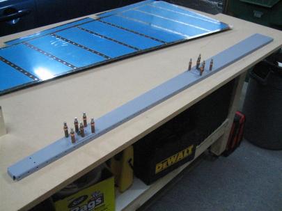
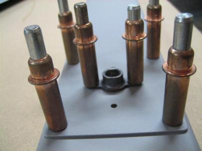
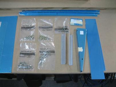
After another half hour or so, I put the spar back on the table and clecoed the R-606PP (Lower Spar Reinforcement) and R-607PP (Middle Spar Reinforcement) to the spar, along with the appropriate K1000-6 nutplates.

I'm getting close to riveting again!

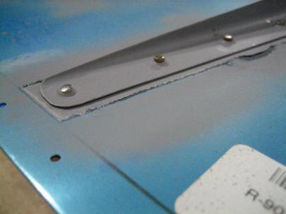
A closeup of the nutplate

I always get so excited when I get to this point.

That was pretty much it, except for more experimentation with the “macro” setting on my camera.

Eh. No reason for this picture. Just experimenting.

1.5 hours today. It felt nice to get a big piece like the spar done.

Prev | Next


Disassembled Rudder to Start Deburring

March 1, 2010

Prev | Next

I liked having the rudder assembled on the workbench over the last day or so. I got to walk by it going in and out of the house admiring how much it looked like an airplane part. I found myself saying, “that’s a rudder” every time I walked by.

Nevertheless, the next step in the construction manual has you disassemble the parts and start the long process of prep for priming and riveting.

Some of the rudder parts, disassembled.

I got everything taken apart yesterday, and then second-guessed myself. I am planning on attaching most, if not all, of the fiberglass fairings with screws and nutplates, which will require the usual dimpling/countersinking of the components. Here’s the catch. Take the rudder bottom fairing attach strips. If I disassemble, deburr, scuff, clean, prime, and rivet them back to the skin/bottom rib, I’ll be drilling through primed parts when I go to install the bottom fairing (and nutplates). Do people re-prime these parts (mainly the holes) after they are riveted to the almost complete rudder?

I’m thinking that maybe I should re-assemble everything, layout the spacing for the fastener attach points now, then go ahead and do the normal disassemble, debur, scuff, clean, prime, and rivet dance. I’m going to pose this question on VAF.

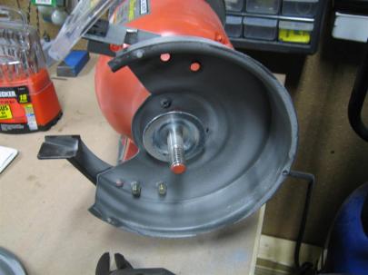
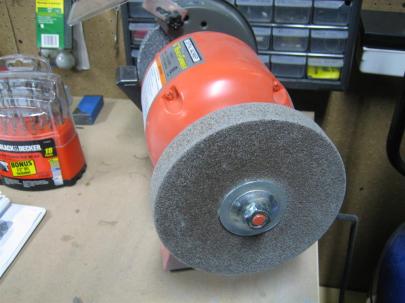
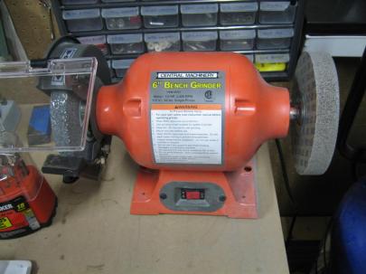
Anyway, with everything disassembled, I started to mark and deburr parts. In preparation for edge finishing, I removed all of the safety covers for the scotchbrite wheel side of my 6″ grinder.

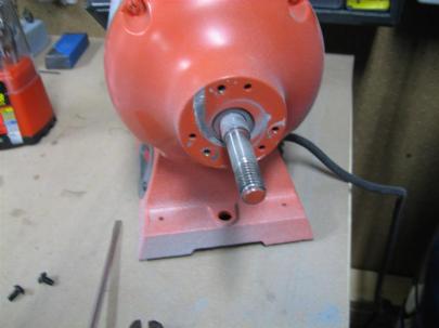
Removed the scotchbrite wheel.

Removed all safety covers.

Reattached scotchbrite wheel.

Ready for some edge-finishing.

Then, I got back to deburring some of the smaller parts. When I finished deburring the holes in a part, I usually take a scotchbrite pad and “mark” the part with a few scuffs. That way, I know all the holes are deburred, and it is time to move on to edge finishing.

I only spent an hour outside today. Had to let the food digest before working out, then it was off to bed.

[yawn] I’m still tired, though.

Prev | Next


Stiffener Prep, Priming, and some Backriveting

February 25, 2010

Prev | Next

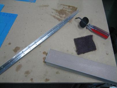
Tonight, I decided I wanted to get started on backriveting the stiffeners. First, I had to finish edge prepping them, and get them primed. Here are my edge prepping tools for these stiffeners.

Permagrit, scotchbrite, an edge deburring tool, and one of the stiffeners. Sorry about the dirty table, that's from me waxing my skis. See the big spot near the top of the picture. That's from me getting wax on the iron, and trying to scrape it off using the table. Maybe I'll turn my benchtop over tonight so I look like a clean builder again.

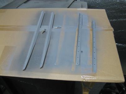
After getting a few of them prepped, I went ahead and started priming.

Stiffeners drying.

Here’s the right skin, ready to accept the stiffeners.

Right skin, with rivets ready to go.

At first, I tried this backriveting extra long double offset rivet set I got from Avery. I don’t really like this thing. With the pressure turned all the way up to 50 psig, the rivets weren’t really setting well, and the plastic sheath was marring the stiffeners.

Here's what I tried the for the first stiffener.

Although the results are good, I ended up switching to another set.

Very pretty. I'm sure some of that marring will come out during polish. Very nice surface, though.

Then I switched sets to a large7/16″ cupped set, which worked well to keep the set (with no plastic sheath) on the rivet as it was being driven, but left some of them with a little bit of a rounded edge. I’m sure this is okay, but need to have someone come look at it.

Still, they look pretty good.

Here’s a better shot. They are okay, but not perfect.

See the slight rounded edge to them? I'm sure that is okay.

I managed to get through 4 stiffeners before I started getting tired and went to bed.

4 of 8 stiffeners done on the right skin.

I pulled the tape off of the exterior side…these look really good. I am excited to maybe polish the rudder so you can all admire my work.

1 hour today, 50 rivets. Wuhoo!

Prev | Next


Started Rudder – Stiffeners

February 16, 2010

Prev | Next

Well, with the vertical stabilizer safely in the airplane storage room, it’s time to get started on another part. Next up, the (infamous) rudder. There are a lot of steps on the rudder that give a lot of builders a lot of trouble. I am confident, but will continue to use other sites on a daily basis before doing any work that evening. That’s worked out well for me so far, so I’m going to keep at it.

First thing’s first, the ceremonial plans change. I still keep the plans on my second workbench. Maybe someday I’ll find a place to actually hang them up.

Drawing 7. The Rudder. (Cue dramatic music.)

I spent a little time trying to figure out whether I will do the stiffener-to-skin dance on both sides at once, or just one side. You can see below that if I had another longer piece of MDF and maybe took my vise off the bench, I could set the skins on opposite corners and maybe do them at once, but I think I’ll just do one at a time, making sure I can reuse the holes I plan to drill into the table. (Drilling, and then clecoing, the stiffeners to the skins all the way into the table will allow me to keep everything very steady. Sounds like a good plan to me, and is pretty much standard given that Van’s suggests doing so in the construction manual.)

I'll have to do one skin at a time. I don't want to get too crowded, and I am not overly concerned with building efficiency.

First step in the manual is to start on the stiffeners. I fished out the bundle of stiffeners (there are two bundles, one set for the rudder, and one set for the elevator) and studied the plans.  For the back side of the stiffeners (with the shallow angle on the right side of the picture below), these are the final cuts, so I need to be careful. For the front side (you can see a little of the front of a stiffener on the left in this picture), only 2 of the 16 stiffeners will be to full length, so the other 14 can be rough cut until I can mark them to final size per the note at the tot of this picture.

Stiffener Trim detail, drawing 7.

Next, I headed inside to sit myself down at the table so I could watch the UNC vs. GT game. I know some of you are panicking right now, but please calm yourselves. While it appears that my winerack is empty (OH MY GOD, NOOOOO!), that is really our third winerack. Rest assured that our two primary wineracks are stocked satisfactorily.

Is that an empty winerack? Don't worry, the hooch is stored in another rack.

Anyway, here’s the stiffener bundle I’m about to break open.

R-915. (I can't think of a funny caption this morning, so all you get is the part number.)

I broke open the bundle and started snipping from center hole to center hole. After a few stiffeners, I started biasing the cuts to the sides of the holes, but only where I was sure that I was going to have to remove more metal later.  Here you can see that on the top part of the cut, I’m lined up with the left side of the slot.

Snip snip.

I included another picture of the angle cut for the front end of the stiffener. Remember, only two of these cuts are for real, as the next step is to chop off varying lengths of stiffener from the front to match up with the pre-drilled holes in the skin.

Snippity Snip snip.

Here’s a rough cut for the front end. See how I am going to have to remove more metal because of the notches. Might as well get closer on the first cut. That’s why I started biasing the cuts to one side after the first few.

The front end of the first stiffener.

First 8 front ends done.

Yikes, those are going to need some edge finishing.

All 16 stiffeners’ front ends done.

That's a spicy stiffener.

Next, I used an admittedly fat sharpie to draw the required cut lines on the aft ends of each of the stiffeners.

Lines drawn, back to snipping.

And here I am using the snips to cut that longer line. Snips aren’t perfect for this task, since they bend the metal, but if you work them correctly, they will only bend the piece you are cutting off. There is kind of a rocking motion you have to feel with each cut. You’ll get it when you try.

Snipping the aft end.

Here’s the first one, done.

I'm a little camera happy today, don't you think?

Then, I finished up the other 15, and was left with these scraps. If I had even the slightest hint of an artistic bone in my body, I would make some comment about how these resulting spirals are king of cool. But I don’t, so I won’t.

Scrap from the latest cuts.

All 16, ready to be devinyled.

Done with those cuts.

Starting to devinyl…

This is going to take forever.

I’m glad I did the devinyling inside. When the vinyl is warm, it comes right off.

Holy crap that's a lot of blue v-......WHOSE TOES ARE THOSE AND HOW DID THEY GET IN THE PICTURE!?

Next, I headed outside to put everything away, but couldn’t resist setting the stiffeners out on the skins.

I'll need to trim some of these, don't you think?

For now, I just drew a thick marker line along the front spar holes. If I cut along these lines, they will still be too long, but at least now I can figure out which hole will be the most forward hole and then use the plans-suggested 1/4″ measurement to draw a nicer cut line.

8 of the 16 stiffeners, ready for final cutting.

One hour of camera-happy warm environment work tonight. Sorry about your bandwidth.

Prev | Next

Finished drilling the HS

January 1, 2010

Prev | Next

Short, but productive day.

It was Jack’s birthday today (he turned 3), so I ran out to Chik-Fil-A to get him is once a year human food treat. A chicken biscuit. Of course, Ginger needed one too (“so she doesn’t feel left out”) and so on, which meant my girlfriend and I also got biscuits. Here are Jack and Ginger.

Jack and Ginger (Jack's on the right) on the beach last summer. Happy Birthday Jack. You're 3 now. Start acting like it.

Anyway, after the birthday festivities (a.k.a. Jack and Ginger inhaling their biscuits), I managed a couple hours on the project. Here, I clamped HS-404 in place after having first marked holes and drilled #40 pilot holes in the aft flange. The instructions have you mark and drill pilot holes in the HS-405, but why drill from aft to forward, hoping you don’t run into edge distance problems when you could drill from forward to aft? For the outboard holes, I did use the HS-405 for pilot holes. You’ll see.

HS-404, with two pilot holes marked and drilled prior to mock-up.

Here are the silver clecos after drilling from forward to aft with my 12″ bit.

Used the #40 pilot holes I previously drilled in HS-404 to drill through HS-702 and HS-405.

Then, I used the previously marked and pilot drilled holes in HS-405 to drill forward through the HS-702 (front spar) and HS-710/714 (reinforcement angles). The 12″ bit really came in handy here.

Then used the #40 pilot holes I made in HS-405 to drill through HS-702 and HS-710 (or HS 714 for the other side). Here, you can see the 12" bit really showing its stuff.

Then, I matchdrilled the rest of the HS-404, which had been clamped in place in the above pictures. After that, I finished match-drilling the rest of the skin for the right side. After you finish and pull the skin off, you can drill the remaining HS-702 holes using the HS-710 and HS-714 angles as guides. Here are the last six holes drilled after pulling off the skin.

Finished drilling HS-710 and HS-714 after removing the skin.

After the skins are pulled off, I’m ready to start prep for final assembly.

After match rilling both skins and finishing the HS-710/HS-714 to HS-702 holes, The skeletons lay ready to disassemble, deburr, dimple, edge finish, surface prep, and prime.

2.0 hours today. Not bad.
Prev | Next


Started on the Practice Kit

September 28, 2009

Prev | Next

Today, I started on the practice kit. The directions point back to (and the kit actually includes) sections 3 and 5 of the construction manual. I threw my extra copies away, I’m going to just keep the ones from the Preview Plans I have.

The kit tells you to make some useful tools before starting. I found 3: A wooden hand seamer, a stand for your practice kit (basically a place to clamp the front spar so the skins stand up vertically) and an assembly with an 11 inch long piece of angle riveted (with various rivets) to two more pieces of 2.25″ x 11″ aluminum sheet. I’m not sure if this is a useful tool or just something to rivet before starting the pretend control surface. Hmm… I’ll make it nonetheless for the practice. I’m going to pass on the hand seamer, but get started on the other two.

Interesting note, the directions tell you that if you don’t have dents, scratches, and mistakes on your practice kit, you aren’t doing it right. Apparently, they want me to get out all of the mistakes now before I start on the real airplane. Right…

Here’s a picture of everything that comes in the kit.

Everything that comes in the kit.

Everything that comes in the kit.

Closeup of the Hardware

Closeup of the Hardware

Closeup of the skins.

Closeup of the skins.

I didn’t get very far on the practice kit. I made it through step one, which is to drill the weird angle assembly in 24 places for the appropriate flush and blind rivets of various sizes. Even the practice kit is going to be slow going. I did learn a ton, though.

  1. Everything is so tiny. I’ve been staring at picture on all the build sites, thinking things were bigger. The -3-3 rivets are TINY! The skins are a lot thinner than I thought they would be.
  2. Don’t take the blue off the skins if you don’t want to scratch the skins. I thought my workbench was clean, but after deburring one of the small sheets, there were small pieces of aluminum everywhere. I slid one of the sheets on the table and scratched the hell out of it.
  3. My cheap clamps are nice, but not perfect. I’ll need to get some higher quality ones. Also, I need to use the duct tape on the clamp face trick. They scratched the hell out of the sheet, too.
  4. I had to measure, mark, and drill the holes. No big deal, but I just noted that they really have you jump right in. I drilled into a spare piece of MDF I had laying around, but I didn’t drill far enough, so the clecos don’t have a fantastic grip. Oh well.
  5. I played around with pressure on the bit while drilling. I learned as a kid that when you have the spiral piece of metal coming off in one piece as you drill, that is the right pressure (which wasn’t that much more than the air drill itself). Anyone have any other advice?
  6. I learned that building is not going to be a piece of cake, but is going to be a lot of fun. That’s kind of a fluffy statement, but it’s true.

Here’s the picture of what I got done last night.

Step one. Drill appropriate holes.

Step one. Drill appropriate holes. Don't make fun of my erroneous markings. The instructions said I have to make mistakes on this practice kit, and not the real airplane, so I made sure there were some errors.

Also, I had to cleco the skin to the end ribs. I don’t know why, but I wanted to do it. I promise not to skip steps in the future.

Top skin cleco'd to the end ribs.

Top skin cleco'd to the end ribs.

Prev | Next


Preview Plans arrived

August 27, 2009

Prev | Next

Last night, the preview plans arrived. They include some welcome pages, an RVator sample, a Van’s accessories catalog, the construction manual, and all the plans from the project printed on 11″ x 17″ paper. They come in a big grey binder.

I sat the binder on the table and stood back and looked at it thinking, “I bet this binder really doesn’t convey the enormity of what I am getting myself into.” After staring for a few minutes, I decided to dive in. I made it through the introductory pages and contruction techniques sections before heading to bed. I’ll start reading the actual construction manual this week and next.

Here’s the plan: the first time through, I just want an overview. The second time through, I am planning on outlining what tools, supplies, etc. I need and when I need them by adding a sheet behind appropriate pages and keeping a list. We’ll see how that goes. I’m trying not to buy tools needed only for the finish kit before building the empennage. More later…

Prev | Next