Over the last couple months, I’ve been eyeing various landing and taxi light setups, trying to figure out what I want to do for my airplane.
I’m not super keen on the leading edge landing/taxi light setup right now, so I want to focus on putting all the lights in the wingtips.
There is a Van’s wingtip landing light kit that puts two MR16 sized bulbs in each wingtip. Supposedly, you can aim one set forward for landing (also recognition) lights, and aim the other set down for taxi.
I’ve read on the forums that people haven’t been too thrilled with this setup using the standard 35W and 50W halogens that van’s provides. Something about not getting enough light on the centerline of the aircraft, where you need it for landing.
I have also read, however, that with the MR16 HID upgrades from somewhere like www.planelights.com or duckworksav.com, there is plenty of light to go around.
Sweet. I’ll go with those. (This is the same as Mike Bullock’s setup, except instead of both sets being 50W, I’ll probably use one set of 50W HIDs for landing, and use a 35W (pronounced “less expensive”) for taxi lights.
But then we come to wig-wag. I think wig-wag (pulsing lights) for the landing lights is a requirement safety wise, so I am planning on incorporating a wig-wag circuit into my landing lights.
I could just wire them in parallel, so you turn the landing lights on, and either wig-wag them or not depending on wig-wag switch position, but because these are going to be HID bulbs, one needs to warm the bulbs up before pulsing. (I’ve read that 25 seconds was used previously on HID flashing circuits, so I’m going to use 30 seconds for now, but I may bump that up based on a crude bulb temperature test I may set up in the future.)
Procedurally, I could just wait 30 seconds after turning the landing lights on before turning on the other switch, pulsing them, but who can remember that 100% of the time? 30 seconds is just about the time it takes between turning the lights on for takeoff and liftoff. This is not the right time to be reaching down for another switch.
I’d rather flip both switches ON, and have them automatically warm up before starting to pulse.
Enter xevision. They have a multiple-hundred-dollar HID flasher box that will work great for this application.
Except I’m an engineer, and I love a good problem to solve, and I don’t have hundreds of dollars laying around.
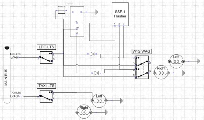
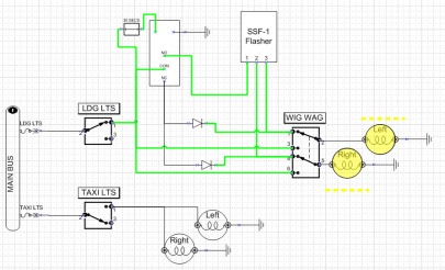
Enter Microsoft Visio and B&C. Using Bob N’s Low Cost Wing Wag Alternative document (page 2.0) as a starting point, I drew up a concept for a landing and wig-wag circuit with a delay timer (haven’t figured out the timer circuit yet, but it’s a relay trigger, so I’m going to simulate it with a switch for now).
Keep in mind, I could combine the functions into a 2-10 switch (similar to page 3.0 of the wig-wag document), but then I couldn’t use the switch-breaker I’m planning to use in place of the regular switch I have depicted. Maybe this circuit is a good candidate for an inline fuse…I’ll sort that out later.
Anyway, here’s the circuit for now (since I am a wiring novice, I’ll have to figure out how to connect 5 wires to one switch terminal later…I know you can’t just bolt them all on there.)
SEPARATE SWITCHES (see below for single switch diagrams)
Oh, and I’ve shown the HID lights here as just normal lights. You get the idea, though.
UPDATE: After testing, I realized I need diodes in here on the flasher side of the 2-3 switch near the NC part of the relay to isolate the two lights. I’ll try to draw them in.
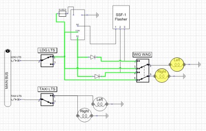
Okay, for the first iteration (see next picture), I’ve turned on the LDG LT switch. +12VDC is now available through the switch, and is going to the following places: 1) to the timer circuit, starting the 30s timer (mechanism TBD), 2) The COM terminal on the SPDT Relay (and therefore through the NC terminal to both of the WIGWIG ON terminals of that switch), and 3) to both of the WIGWIG OFF terminals of that switch.
Summary, the 30s timer as started, and both landing lights are on steady.
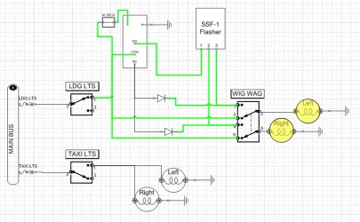
At this point, if we turn the WIGWAG switch ON (see next picture), the landing lights are still getting power, but through the NC terminals of the relay, so they are both still on steady. This is good, because we don’t want them to pulse before the 30s of warm up time as elapsed.
Okay, let’s turn the WIGWAG switch back off, and let the 30 seconds elapse. Now. +12VDC is now available through the switch, and is going to the following places: 1) to the timer circuit, which has now closed the relay, 2) The COM terminal on the SPDT Relay (and therefore through the NO terminal to the SSF flasher, and then to both of the WIGWIG ON terminals of that switch), and 3) to both of the WIGWIG OFF terminals of that switch.
Summary, the 30s timer has elapsed, but since the WIGWAG switch is off, we are still getting steady lights.
Finally, we move the WIGWAG switch to ON, and the lights are being powered through the LDG LT switch, the trigger relay, which closes the SPDT relay, the SSF flasher, and the WIGWAG switches ON terminals.
Summary. Pulsing lights.
Basically, the timer won’t let power go through the flasher until 30s after the landing lights are turned on.
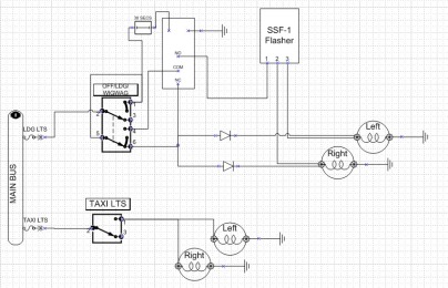
The trick now will be to figure out whether I want them on one ON-ON-ON switch. (Switch positions would be OFF-LDG ONLY-WIG WAG.)
Here’s the logic table.
|
||||||||||||||||||||||||||||||||
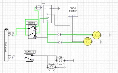
SINGLE SWITCH
Of course, I was motivated enough to figure it out.
I think this will work.
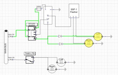
LDG Only (Before 30s...if this was after 30 seconds, the timer would close the relay, but since it is unpowered, it wouldn't matter.)
Now, I figure I’m missing some diodes or something somewhere. Anyone have any suggestions?



My eyes totally glazed over after the first diagram. No suggestions on the diodes from me! I love reading these :-)